-9-
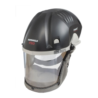
EN - AIR/PRO
• Release nuts and screw and remove the headband
from the helmet.
• Assemble anti-rotating cap and screw retainer to
headband noting that Anti- rotating caps are marked
‘L’ (left) and ‘R’ (right)
• Position the headband in the helmet ensuring that the
tabs on the anti-rotating cap locate in the helmet.
• Fit screws through retainer, anti -rotating cap and visor
secure with nuts.
Air filter replacement
Lift the cover as shown in (Fig.1) Replace air filter as
shown in (Fig.9)
• Hold the neck of the fitted air filter and push firmly
towards sealing face to release from securing tabs and
lift filter upwards to remove. Discard appropriately.
• Locate new air filter against sealing face. Push firmly
toward sealing face and downwards. Filter will click
into in securing tabs. Ensure the rear locating tag is
engaged in the slot and the filter lays parallel to the
chassis.
• Refit helmet cover.
CAUTION:
Dust on the respirator or filter from usage should be
handled in a safe manner in accordance with the
manufacturer’s safety data information.
Fan/motor assembly replacement
Lift the cover as shown in (Fig.1)
Replace fan/motor assembly as shown in (Fig.10)
• Disconnect fan/motor electrical lead from the
electronics unit.
• Remove the two screws securing the front air duct. Lift
the air duct from locating lip and pull fan/motor from
rear air duct. Separate fan/motor from front air duct.
• Fold back both seals on replacement fan/motor
assembly. With electrical lead point downwards locate
with front air duct and secure by unfolding seal over
duct.
• Connect electrical lead to electronics unit.
• Locate front air duct in lip and fan/motor with rear
air duct, tuck excess cable under fan/motor unit and
unfold seal to secure. Secure air duct with screws.
• Ensure both seals are fully engaged with ducts and a
re fully unfolded, failure to do so may compromise the
unit’s performance.
Electronics unit
Lift the cover as shown in (Fig.1)
Replace electronics unit as shown in (Fig.11)
STORAGE
The equipment should be stored in dry, clean conditions
away from direct sunlight, sources of heat, petrol and
solvent vapours.
Store the equipment within the temperature range +5°C
to +40°C and the humidity range 0 -90%.