6
INSTALLATION AND START UP
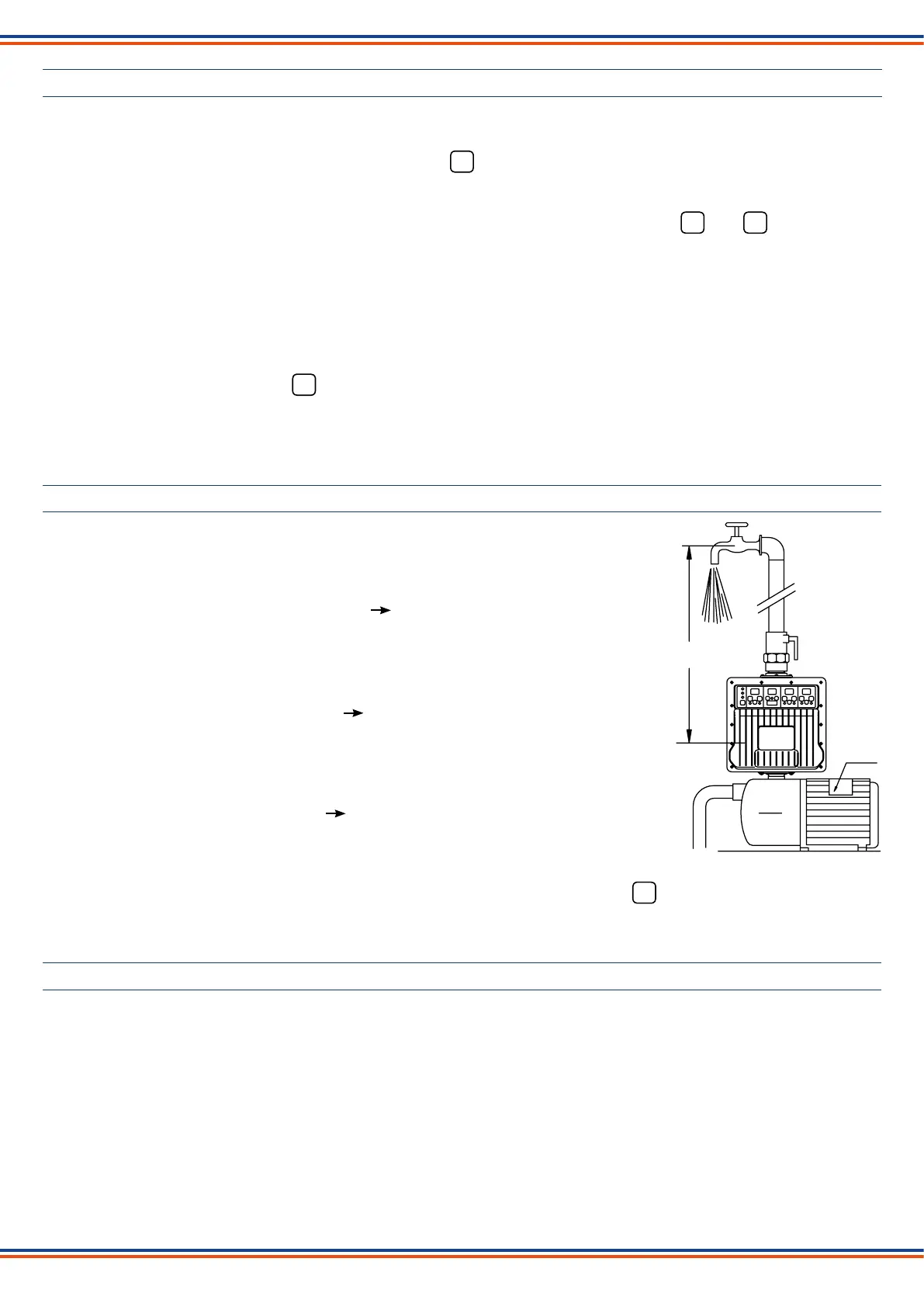
Installthedeviceinverticalpositiondirectlyonthepumporbetweenthepumpandtherstuser.
Make all electrical connections following the diagrams below and connect to main power supply.
On the control panel the green “Power on” led and the red led on the switch will light up.
Blinking dashes will appear on all the displays while the device carries out the set-up operations. When the set-up is
completed the factory-set current and pressure values will appear on the display (CURRENT 1,5 A - SYSTEM PRESSURE
3.0 bar - CUT-IN PRESSURE 1.5 bar), the “Current” display will start blinking and the yellow and led will light up.
The value of the pressure of the system will appear on the Pressure display.
Set the current value absorbed by the motor as indicated on the relative nameplate.
To adapt the plant to the desired operations, different pressure values can be set than the factory-set ones: system
pressure 3 bar - cut-in pressure 1.5 bar.
The set pressure value of the system must be lower than the maximum effective pressure generated by the pump and
compatible with the desired pump delivery.
The set cut-in pressure value must be higher than the pressure extended on the device by the water column height.
After setting the values, press the button of the switch (green led on) to start.
When the pump is in operation the real value of the current absorbed by the motor will appear on the Current display.
In case of a temporary blackout, the device will automatically rearm once the electricity returns.
EXAMPLE OF PARAMETERS SETTING
- CURRENT
Adjustment steps 0,5 A up to 10 A - 1 A over 10 A
Set the value immediately over the value of A
indicated on the nameplate.
Example: motor current (on nameplate) 6,3 A max 6,5 A
- SYSTEM PRESSURE
Adjustment step 0,5 bar.
Set the desired value lower than the maximum
effective pressure generated by the pump.
Example: maximum pump pressure 9 bar max 8,5 bar
- CUT-IN PRESSURE
Adjustment step 0,1 bar
Set the desired value higher of at least ~0,5 bar
than the pressure exerted by the water column.
Example: water column pressure 1 bar min 1,5 bar
It is possible to change the set pressure values even while the pump is operating.
Before changing the value of the absorbed current (amperes) of the motor, press the button (red led on) of the switch
on the current display.
10 mt - 1 bar
90 mt
6,3 A
9 bar
AUTOMATIC RESTART AND ANTI-JAMMING FUNCTION
In case of stopping due to a water shortage, the device will automatically make 10 double attempts to rearm over the 24
hours following the failure, each lasting approximately 5 seconds to allow the pump and the system to reload if possible.
After the last failed rearming attempt, the device will remain permanently in alarm (red “Failure” led blinking) pending
manual rearming by pressing the Restart button.
The user can try to rearm the device at any time by pressing the Restart button.
If for any reason the pump remains idle for 24 consecutive hours, the device will carry out a start up of the pump motor for
about 5 seconds.
OFF
A
P
ON
OFF
 Loading...