16
MAINTENANCE
STUB SHAFT ON MODEL CC4410 PUMPS
INSTALLATION
If you purchased a MODEL C4410 pump LESS MOTOR, and are installing your own motor, or if you
are CHANGING MOTORS, please note following special instructions for proper assembly:
C4410 pump shafts utilize six set screws to secure the stub shaft to the motor shaft. Because some
of these six set screws are of the "dog point" design, it is necessary to drill "F" (.257) diameter holes -
3
/16" (5mm) deep into the motor shaft when assembling the pump.
C4410 pumps manufactured between December 1988 and June 1989 feature stub shafts designated
as Type I on illustration below (Figure 6). Three of the six set screws on Type I shafts are "dog
point", and must be installed as noted above. C4410 pumps manufactured after June 1989 feature
stub shafts designated as Type II on illustration below. Two of the six set screws on Type II shafts
are "dog point", and must be installed as noted above.
These holes must be drilled AFTER the stub shaft is properly located on the motor shaft. Proper
location is with
1
/16" (1.5mm) clearance between the impeller back-face and the inside face of the
backplate. Holes are drilled into the motor shaft in line with the set screw holes of the stub shaft.
DRILL BUSHING #C4410DB-06 should be used when drilling the holes, to assure correct placement.
Effective 4/1/89, one #C4410DB-06 Bushing is included with each C4410 pump shipped from Tri-
Clover LESS MOTOR. Additional bushings are available upon request from Tri-Clover, if you require
for later field servicing of the pump.
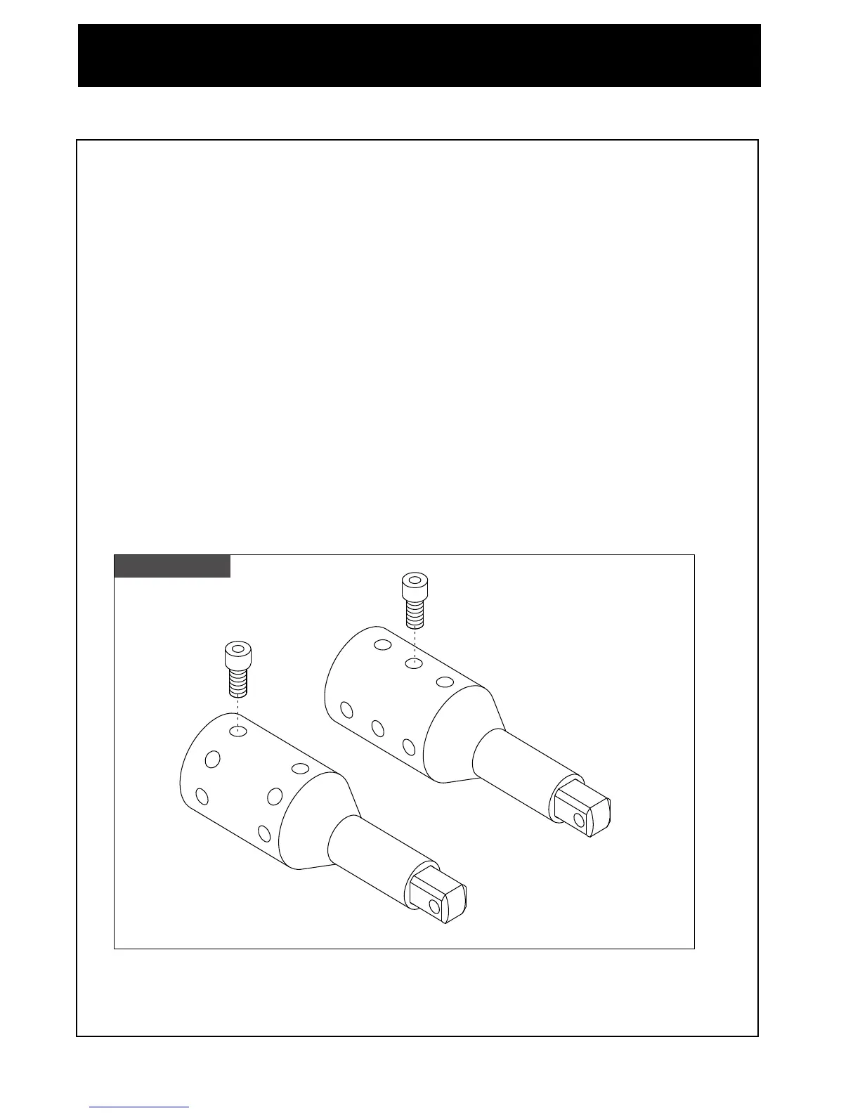
Figure Six
Type I Shaft:
Insert drill bushing in holes A, B, C,
and drill into motor shaft
#C4410DB-06 Drill
Bushing
A
A
Type II
Type I
Type II:
Insert drill bushing in holes A,
B and drill into motor shaft
B
C
B