15
CHAPTER 3
CHAPTER 3 - INSTALLATION - WIRING
3.1. Wiring Requirements
Electrical shock hazard can cause substantial
property damage, serious injury, or death.
Disconnect power before installing and/or
servicing.
1. All wiring must be a minimum of 18 gauge and in-
stalled in accordance with:
• U.S.A. - National Electrical Code and any other
national, state or local code requirements hav-
ing jurisdiction.
• Canada - C.S.A. C22.1 Canadian Electrical Code
Part 1 and any other national, provincial and lo-
cal code requirements having jurisdiction.
2. If original wire supplied with appliance must be re-
placed, Type 90ºC or its equivalent must be used.
3. Refer to control component instructions packed
with boiler for application information.
4. An optional service switch may be installed in water
heater electrical circuit. This switch would only shut
o the water heater, not the home heating system.
Do not shut o water heater if there is a chance of
freezing.
5. All electrical contacts shown do not have power
applied - o the shelf condition. See pages 15 to 19.
3.2. Circulators
Priority relay must be sized for total amp draw of all cir-
culators.
WARNING
3.3. Zone Valves
Transformer must be sized for maximum load of all
zone valves.
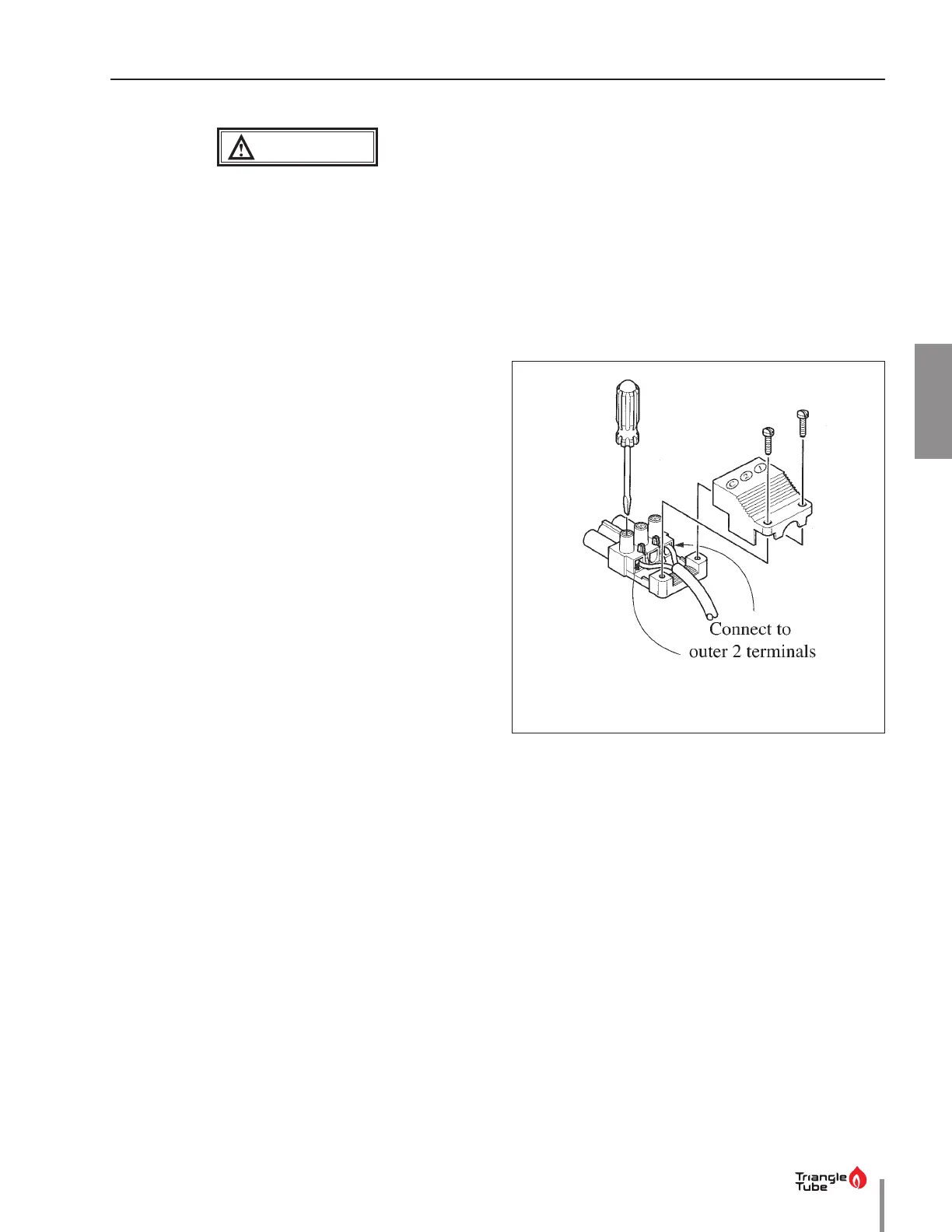
3.4. Snap Set Connection
For easy wiring between water heater thermostat and
boiler controls see wiring diagrams in following pages
(refer to Fig. 16 on page 16 thru Fig. 22 on page 19).
Make sure snap set is rmly snapped together after wir-
ing.
Fig. 15 - Snap Set Wiring



 To Next Page