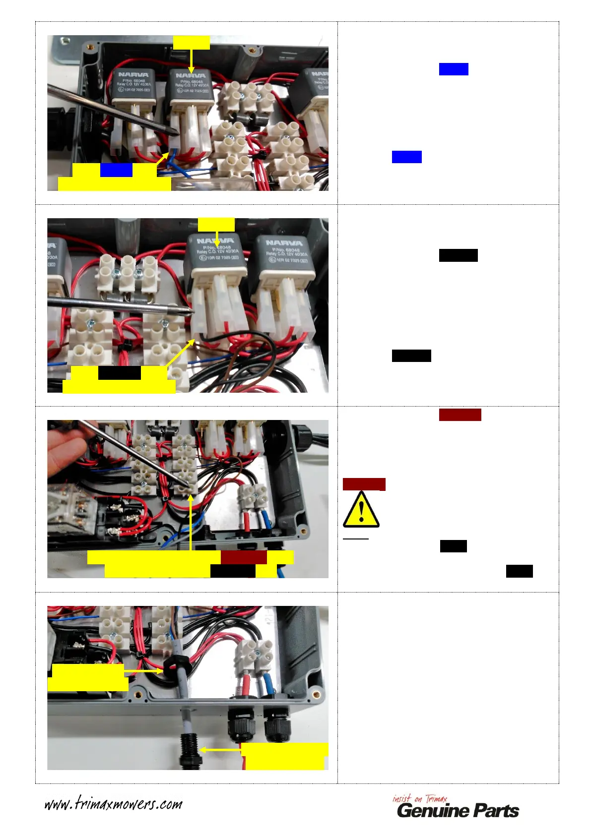
Identify and trace the BLUE wire running from
the I.L.S. Control Cable to Relay 3.
Take note of the termination point of this wire,
this is labelled on this Relay as POSITION 85.
Slide the Spade Terminal off of the Relay to
release the BLUE wire.
Identify and trace the BLACK wire running
from the I.L.S. Control Cable to Relay 4.
Take note of the termination point of this wire,
this is also labelled on this Relay as
POSITION 85.
Slide the Spade Terminal off of the Relay to
release the BLACK wire.
Identify and trace the BROWN wire running
from the I.L.S. Control Cable to the Screw
Connector shown.
Take note of the termination point of this wire.
Slacken the retaining Screw to release the
BROWN wire.
Note:
DO NOT remove the Black Wire that shares
this same Screw Connector Position!
Nip the Screw back up to ensure this Black
Wire Stays in place!
At this stage, ALL FOUR of the I.L.S. Control
Cable Wires should be disconnected from the
Command Module.
Undo the INNER Cable Gland Nut and slide
the Cable Gland clear of the Command Module
Enclosure.
Slide BLUE wire
Terminal off of Relay 3
Slide BLACK Wire
Terminal off of Relay 4
Slacken this screw, remove BROWN wire,
DO NOT remove the BLACK wire
Undo the Inner
Cable Gland Nut
Slide Cable Gland
out of Enclosure
 Loading...