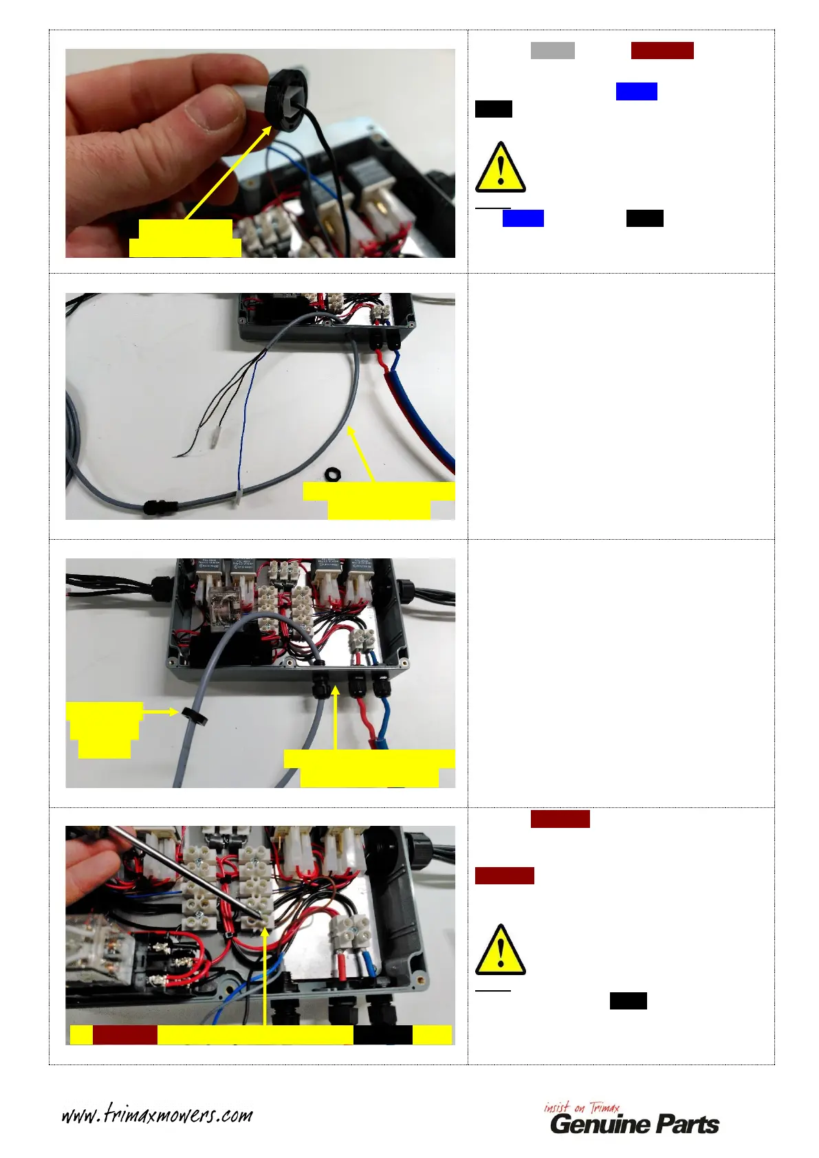
Feed the GREY wire and BROWN wire
through the Inner Cable Gland Nut.
One at a time, feed the BLUE wire and the
Black Wire through the Inner Cable Gland Nut.
One shown.
Note:
The BLUE wire and the Black wire are a tight
fit through the Inner Cable Gland Nut due to
the Spade Terminals, however they do fit!
Remove the I.L.S. Control Cable from the
Command Module Enclosure.
Discard to I.L.S. Control Cable.
Collect your replacement I.L.S. Control Cable.
Remove the supplied Inner Gland Nut using the
same method as before.
Feed the free end of the Control Cable through
the FRONT of the Command Module
Enclosure.
Refit the Inner Cable Gland Nut to the free end
of the Control Cable, leave this loose at this
stage as the Cable Gland will be secured once
the four wires have been connected.
Feed the BROWN wire running from the I.L.S.
Control Cable into the Screw Connector shown.
Tighten the retaining Screw to secure the
BROWN wire.
Give the two wires a gentle pull to ensure that
they are secured correctly!
Note:
DO NOT remove the Black wire that shares
this same Screw Connector Position, ensure
that this wire is still secure after tightening the
Screw!
Remove Inner
Cable Gland Nut
Remove Control Cable
from Enclosure
Feed replacement Control
Cable into Enclosure
Inner Cable
Gland Nut
in place
Fit BROWN wire here, DO NOT remove BLACK wire!
 Loading...