www.highwayguardrail.com 12 Revised: October 5, 2009
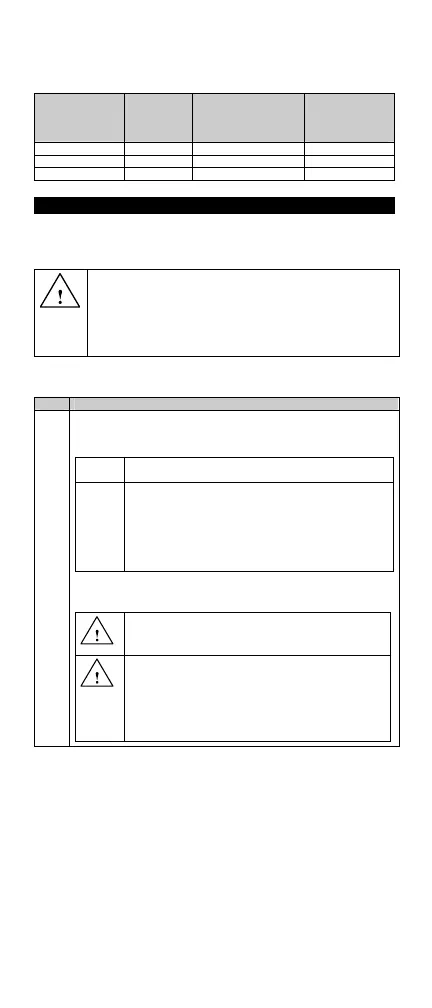
curve a distance equal to the line guardrail offset plus 1 foot
maximum in Table 1. (See state/specifying agency drawings for
details.)
ET™ Length Outside the
Curve Max
Offset
Inside the Curve
With a Radius
Greater Than 1000
Feet Max Offset
Inside the Curve
With a Radius
1000 Feet or
Less Max Offset
50 Feet
2 Feet 2 Feet 1 Foot
37 Feet 6 Inches
1.5 Feet 1.5 Feet 1 Foot
25 Feet
1 Foot 1 Foot 1 Foot
Table 1
POST INSTALLATION
Complete the following steps when installing wood CRT posts, foundation
tubes with wood posts, HBA™ posts, and SYTP™. When installing posts
in rigid pavement, see the POST INSTALLED IN RIGID MATERIAL
section.
WARNING: Ensure that the proper Leaveout (specified area of
open space in the pavement) around the posts is reserved and
filled with state/specifying agency approved backfill material that will
not prevent movement, for any posts installed in rigid pavement
such as any thickness of concrete or asphalt. Failure to follow this
warning could result in serious injury or death in the event of a
collision.
INSTALLING THE WOOD CRT POSTS
Complete the following steps to install the wood CRT posts:
Step Actions
1.
Install the wood posts (PN-4063B) at locations required for the
systems, spaced at 6' 3" (1270 mm) apart. Select Option A or
Option B to install the CRT posts.
Option
A
Drive posts into the ground.
Option
B
1. Drill 12” (300 mm) maximum diameter pilot
holes approximately 44" (1120 mm) deep.
2. Insert the 6' 0" (1830 mm) wood posts into these
holes.
3. Backfill the holes with compactable materials in
6" (150 mm) lifts and compact with pneumatic
equipment to optimum compaction.
Note: In either option within Step 1, the bottom of the upper 3
1
/
2
"
(90 mm) hole in the post is approximately at the finished grade.
WARNING: Do NOT install 6’0” CRT post at location 1.
Failure to follow this warning could result in serious injury
or death in the event of a collision.
WARNING: Ensure that the proper Leaveout (specified
area of open space in the pavement) around the posts is
reserved and filled with state/specifying agency approved
backfill material that will not prevent movement, for any
posts installed in rigid pavement such as any thickness of
concrete or asphalt. Failure to follow this warning could
result in serious injury or death in the event of a collision.
Revised: March 2010
 Loading...