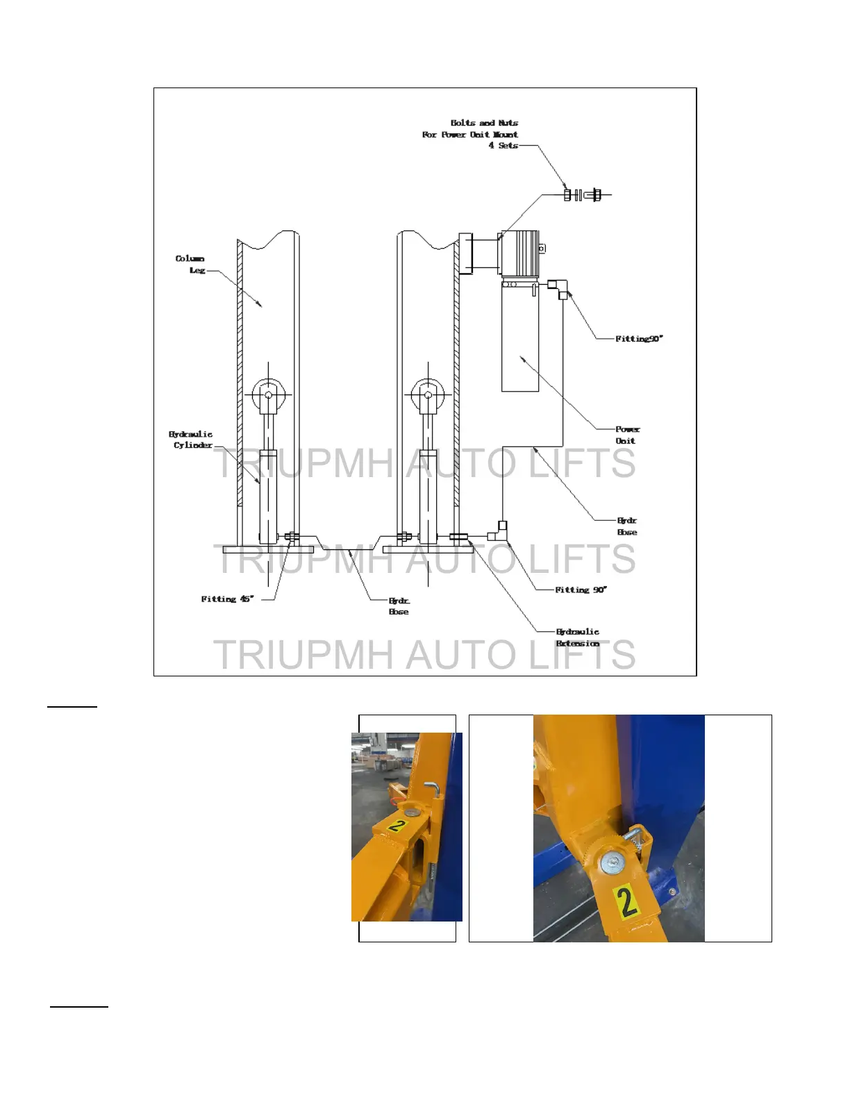
Hose Route Diagram
Fig. 18
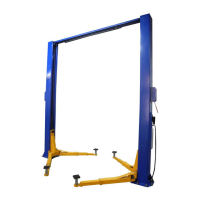
Fig. 16
STEP 9: (Installing Lifting Arms & Arm Restraints)
Install the lifting swing arms on the
carriages using the included 1-1/2”
diameter pins. Check for proper
engagement of the arm restraint. The
rack on the arm restraints should fully
engage the gear on the arm (Figs. 17-19).
Fig. 18
Fig.17
STEP 10: Lay Mount Drive-Over Base Plate on the floor between the posts
11
NOTE: Double Telescoping Arms (3pc) go toward the front of the vehicle; Single Telescoping Arms (2pc) go to the rear.
Call 866-563-5438 For Help
TRIUPMH AUTO LIFTS
TRIUPMH AUTO LIFTS
TRIUPMH AUTO LIFTS