1430
Circuit Diagrams
Glossary of Circuit Diagram Symbols
The following is a description of the symbols and information found in the circuit
diagrams for this model.
Wire colours and connector pin references shown in the illustrations below are
examples and may differ from those contained in circuit diagrams for this model.
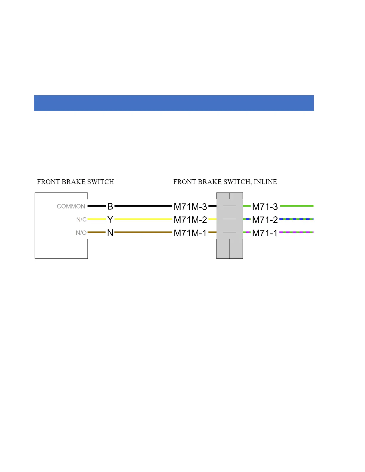
Components with a Fly lead and an In-line Connector
The illustration shows an example of a component with a fly lead and an in-line
connector.
The component is represented by a white box, with fly lead wires leading to an in-line
connector (shaded grey). Information provided with the component includes:
• The component name - located above the component.
• A function reference for each terminal - located inside the component, adjacent
to the connecting wire (provided in English only).
• Wire colour references - located on each wire.
• An in-line connector name - located above the in-line connector.
• A component and pin number reference - located on each wire entering the in-
line connector.