CLUTCH
I.
GENERAL
DATA
47.LU\I:
TRAVELAVAILABLE
Model
A
6
G
9".
Hydraulically operated from
twin
bore
master cylinder which incorporates the
brake master cylinder.
Ball bearing release bearing.
Clearance between ball bearing release bear-
ing and release
levers-.0625".
TO
RELEASECLUTCH
Nine, 120-130 lb.
R ream
thrust springs.
IN
TU~S
DlRECrlON
Single dry plate with six springs.
All
six
springs cushion the driving torque, whilst
three (grey in colour) cushion the over
run.
Free travel on clutch pedal
=
.820.
CIearance between piston rod and master
!
cylinder piston
=
.030.
End float in Slave Cylinder fork assembly
=
.079".
Height of release lever tip from face of
flywheel
=
1.895".
Long portion of hub towards Gearbox.
2.
TOOL
DATA
Borg and Beck Gauge Plate No. CG.192.
Land Thickness
=
.33OV (see uage
13).
-
\
S"
Churchill ~ool S~acers
......
......
NO.
3
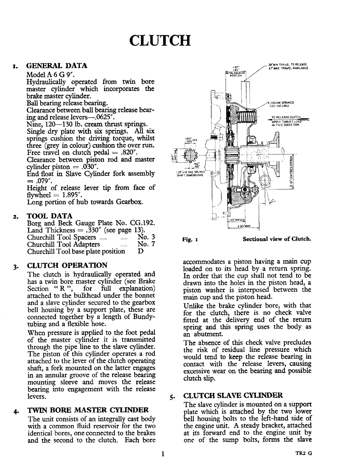
Fig.
I
Churchill Tool ~ha~ters
......
No.
7
Churchill Tool base plate position
D
Sectional
view
of
Clutch.
3.
CLUTCH OPERATION
accommodates a piston having a main cup
loaded on to its head by a return spring.
The clutch is hydraulically operated and
In order that the cup shall not tend to be
has a twin bore master cylinder (see Brake
drawn into the holes in the piston head, a
Section
"R
",
for
full
explanation) piston washer is interposed between the
attached to the bulkhead under the bonnet
main cup and the piston head.
and a slave cylinder secured to the gearbox
bell housing by a support plate, these are
Unlike the brake cylinder bore, with that
connected together
by
a length of Bundy-
for the clutch, there is no check valve
tubing and a flexible hose.
fitted at the delivery end of the return
spring and this spring uses the body as
When pressure is applied to the foot pedal
an abutment.
of the master cylinder it is transmitted
through the pipe line to the slave cylinder.
The absence of this check valve precludes
The piston of this cylinder operates a rod
the risk of residual line pressure which
attached to the lever of the clutch operating
would tend to keep the release bearing
in
contact with the release levers, causing
shaft, a fork mounted on the latter engages
in
an annular groove
of
the release bearing
excessive wear on the bearing and possible
mounting sleeve
and
moves the release
clutch slip.
bearing &to engagement with the release
levers.
5.
CLUTCH SLAVE
CYLINDER
The slave cylinder is mounted on a support
4.
TWIN
BORE
MASTER
CYLINDER
plate which is attached by the two lower
The unit consists of an integrally cast body
bell housing bolts to the left-hand side of
with a common
fluid
reservoir for the two
the engine unit.
A
steady bracket, attached
identical bores, one connected to the brakes
at its forward end to the engine unit by
and the second to the clutch. Each bore
one of the sump bolts, forms the slave
 Loading...


