CLUTCH
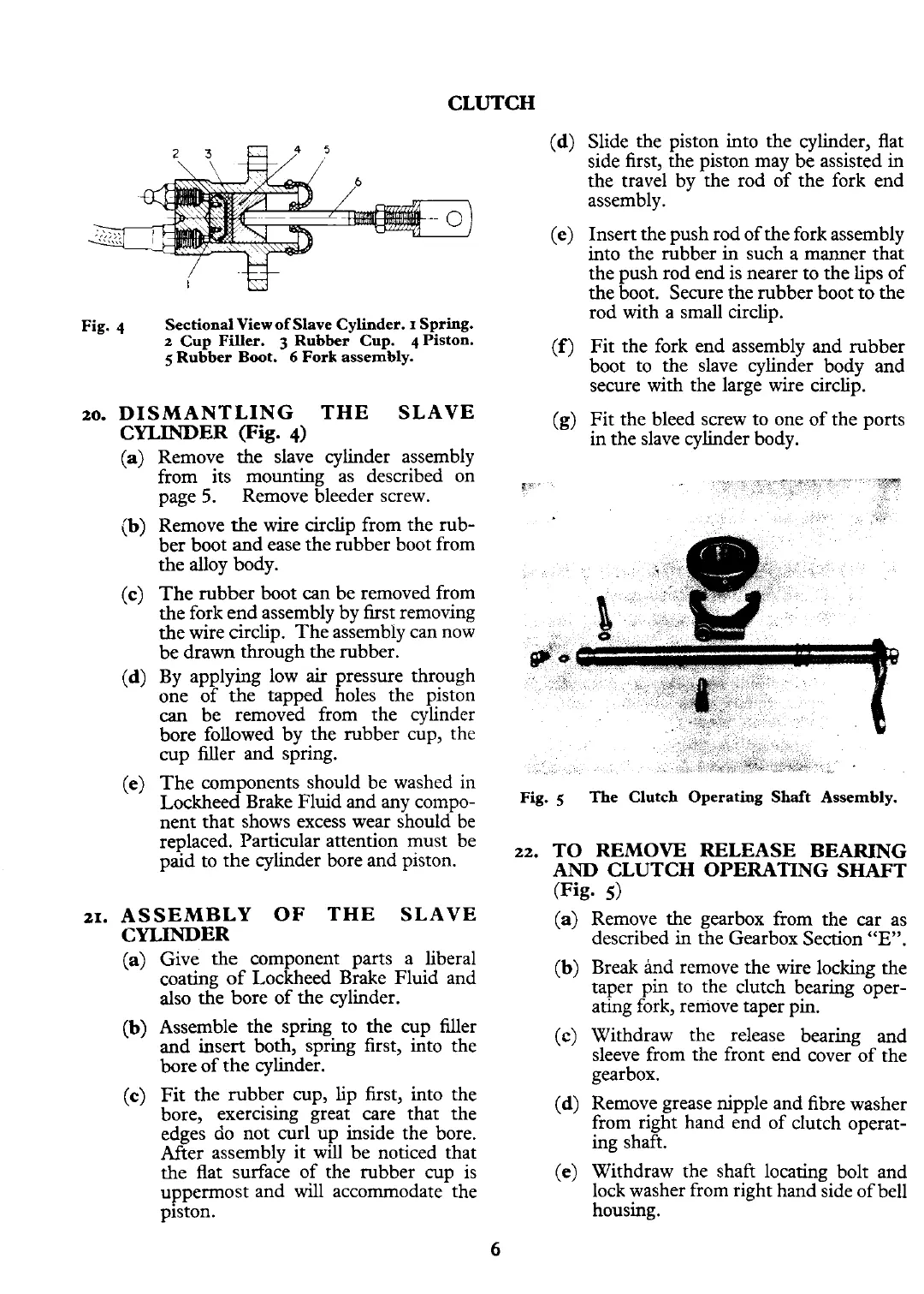
Fig.
4
Sectional View of Slave Cylinder.
I
Spring.
2
Cup Filler.
3
Rubber Cup.
4
Piston.
S
Rubber Boot.
6
Fork assembly.
20.
DISMANTLING THE SLAVE
CYLINDER
(Fig.
4)
(a)
Remove the slave cylinder assembly
from its mounting as described on
page
5.
Remove bleeder screw.
(b)
Remove the wire circlip from the rub-
ber boot and ease the rubber boot from
the alloy body.
(c)
The rubber boot can be removed from
the fork end assembly by first removing
the wire circlip. The assembly can now
be drawn through the rubber.
(d)
By applying low
air
pressure through
one of the tapped holes the piston
can
be removed from the cylinder
bore followed by the rubber cup, the
cup filler and spring.
(e)
The components should be washed in
Lockheed Brake Fluid and any compo-
nent that shows excess wear should be
replaced. Particular attention must be
paid to the cylinder bore and piston.
21.
ASSEMBLY OF THE SLAVE
CYLINDER
(a)
Give the component parts
a
liberal
coating of Lockheed Brake Fluid and
also the bore of the cylinder.
(b)
Assemble the spring to the cup filler
and insert both, spring first, into the
bore of the cylinder.
(c)
Fit the rubber cup, lip first, into the
bore, exercising great care that the
edges do not curl up inside the bore.
After assembly it
will
be noticed that
the flat surface of the rubber cup is
uppermost and
will
accommodate the
piston.
(d)
Slide the piston into the cylinder, flat
side first, the piston may be assisted in
the travel by the rod of the fork end
assembly.
(e)
Insert the push rod of the fork assembly
into the rubber in such a manner that
the push rod end is nearer to the lips of
the boot. Secure the rubber boot to the
rod with a small circlip.
(f)
Fit the fork end assembly and rubber
boot to the slave cylinder body and
secure with the large wire circlip.
(g)
Fit the bleed screw to one of the ports
in the slave cylinder body.
Fig.
5
The
Clutch Operating Shaft Assembly.
22.
TO REMOVE RELEASE BEARING
AND CLUTCH OPERATING SHAFT
(Fig.
5)
(a)
Remove the gearbox from the car as
described in the Gearbox Section
"E".
(b)
Break and remove the wire locking the
taper pin to the clutch bearing oper-
ating fork, remove taper pin.
(c)
Withdraw the release bearing and
sleeve from the front end cover of the
gearbox.
(d)
Remove grease nipple and fibre washer
from right hand end of clutch operat-
ing shaft.
(e)
Withdraw the shaft locating bolt and
lock washer from right hand side of bell
housing.