CLUTCH
(f)
Holding the clutch operating fork
with-
draw the shaft from the left.
(g) Remove spring and grease nipple with
fibre washer from lever end of shaft.
NOTE-To effect the removal of the shaft
from cars prior to Commission No.
TS.
41
1, there is no necessity to remove
the grease nipple (operation d) and the
shaft locating bolt (operation
e)
is sit-
uated on the left hand side of the bell
housing.
23.
TO REPLACE CLUTCH OPERATING
SHAFT AND RELEASE BEARING
The replacement of the clutch operating
shaft and release bearing is the reversal of
the removal. It will be found, however, that
light pressure will be necessary to compress
the spring on the operating shaft to insert
and tighten the shaft locating bolt.
When fitting the ball bearing release bearing,
locate the pegs of the operating fork in the
groove of the bearing. Secure the operating
fork to the shaft with the taper pin and lock
'the head with wire.
24.
REMOVAL OF
THE
CLUTCH
FROM FLYWHEEL WITH GEAR-
BOX REMOVED
(a) Slacken the six holding bolts, in the
outer rirnof the cover pressing, a turn at
a time by diagonal selection until the
thrust spring pressure is relieved.
(b) Remove the six bolts and lift away the
cover assembly and driven plate assem-
bly from the two locating dowels.
(c)
Inspect the two dowels in the flywheel
for looseness and burrs and replace if
necessary.
25.
REPLACEMENT OF CLUTCH TO
FLYWHEEL
(Fig. 6)
(a) Place the driven plate assembly on the
flywheel with the larger portion of the
splined hub towards the gearbox.
Centralise this plate with the Churchill
Tool No.
20s.
72
or the splined
portion of a constant pinion shaft.
(b) Fit the cover assembly over the driven
plate and locate it on the two dowels in
the face of the flywheel.
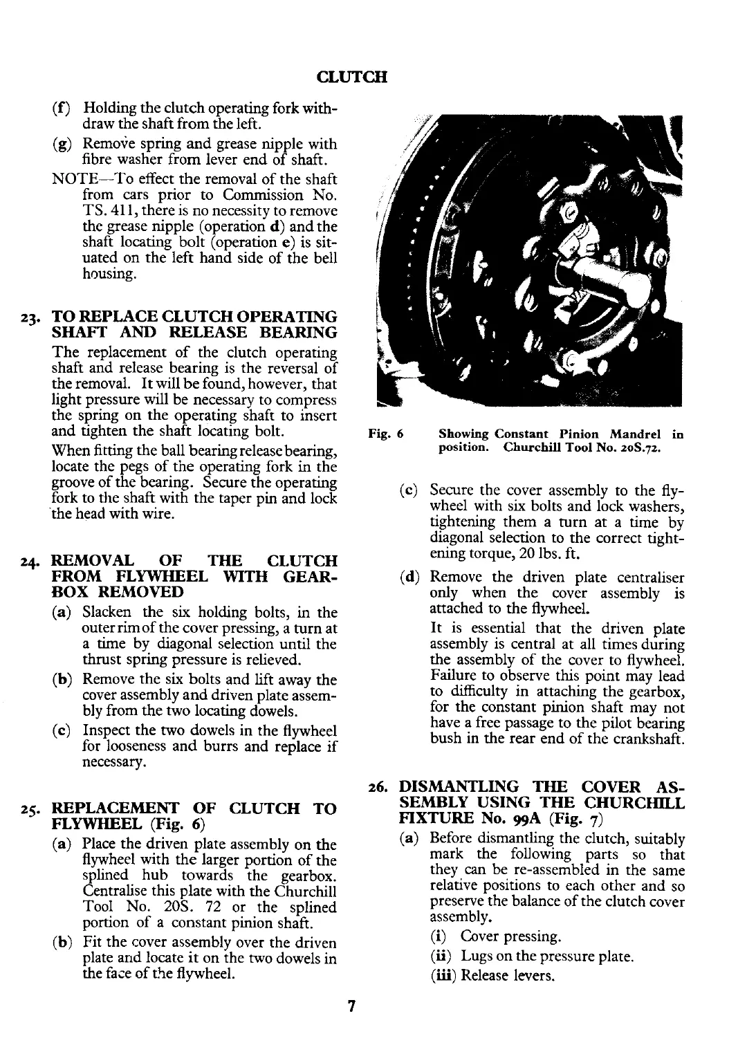
Fig.
6
Showing Constant Pinion Mandrel in
position. Churchill Tool No. 2oS.72.
(c) Secure the cover assembly to the fly-
wheel with six bolts and lock washers,
tightening them a turn at a time by
diagonal selection to the correct tight-
ening torque,
20 lbs. ft.
(d) Remove the driven plate centraliser
only when the cover assembly is
attached to the flywheel.
It is essential that the driven plate
assembly is central at all times during
the assembly of the cover to flywheel.
Failure to observe this point may lead
to difficulty in attaching the gearbox,
for the constant pinion shaft may not
have a free passage to the pilot bearing
bush in the rear end of the crankshaft.
26.
DISMANTLING
THE
COVER AS-
SEMBLY USING THE CHURCHILL
FIXTURE No.
ggA
(Fig.
7)
(a) Before dismantling the clutch, suitably
mark the following parts so that
they
can
be re-assembled in the same
relative positions to each other and so
preserve the balance of the clutch cover
assembly.
(i) Cover pressing.
(ii)
Lugs on the pressure plate.
(iii)
Release levers.
 Loading...


