CLUTCH
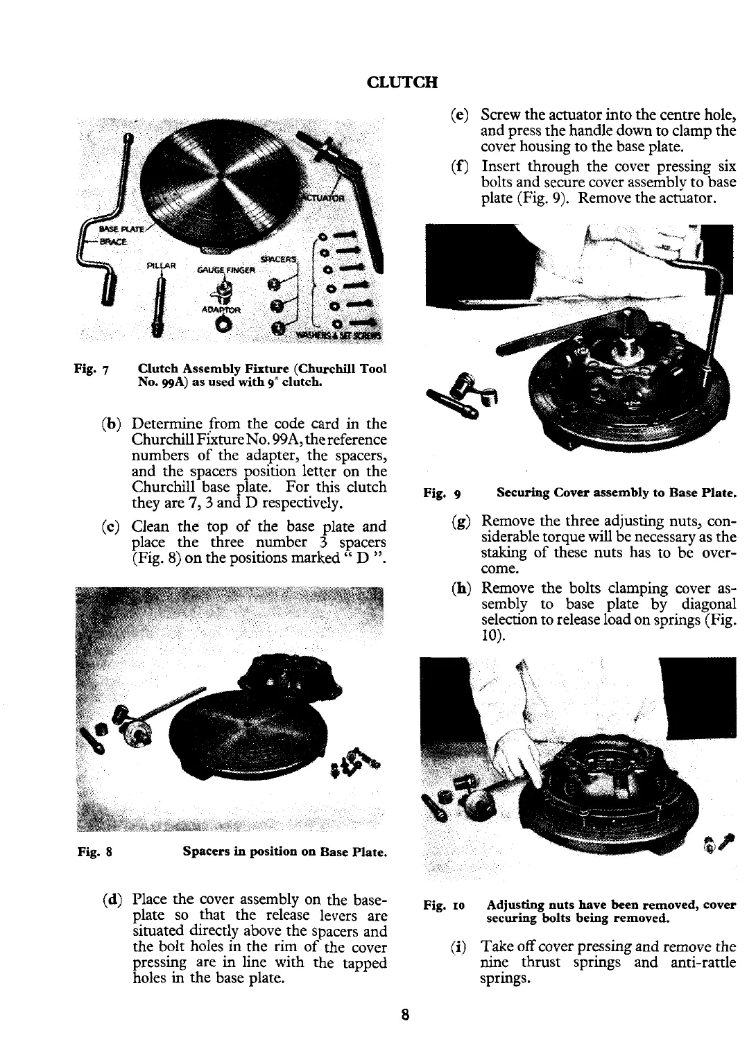
Clutch Assembly Fixture (Churchill Tool
No. ggA) as used with
g"
clutch.
Determine from the code card in the
Churchill Fixture No. 99A,the reference
numbers of the adapter, the spacers,
and the spacers position letter on the
Churchill base plate. For this clutch
they are
7,3
and D respectively.
Clean the top of the base plate and
place the three number
3
spacers
(Fig.
8)
on
the positions marked
"
D
".
Screw the actuator into the centre hole,
and press the handle down to clamp the
cover housing to the base plate.
Insert through the cover pressing six
bolts and secure cover assembly to base
plate (Fig. 9). Remove the actuator.
Securing Cover assembly to Base Plate.
Remove the three adjusting nuts, con-
siderable torque
will
be necessary as the
staking of these nuts has to be over-
come.
Remove the bolts clamping cover as-
sembly to base plate by diagonal
selection to release load on springs (Fig.
10).
Spacers
in
position on Base Plate.
Place the cover assembly on the base-
plate so that the release levers are
situated directly above the spacers and
the bolt holes in the rim of the cover
pressing are in line with the tapped
holes
in
the base plate.
Fig.
10
0)
Adjusting nuts have been removed, cover
securing bolts being removed.
Take off cover pressing and remove the
nine thrust springs and anti-rattle
springs.