CLUTCH
(j) Lift up inner end of release lever and
disengage the strut. Repeat procedure
for 2nd and 3rd levers.
(k) Gripping the tip of the release lever and
the eye bolt lift out the assembly from
the pressure plate. Repeat procedure
for 2nd and 3rd levers.
(1)
Remove the eye bolts from release
levers and take out pins. Remove the
struts from pressure plate.
27.
ASSEMBLY OF COVER PLATE
ASSEMBLY USING THE
CHURCHILL FIXTURE
No.
ggA
Before assembling a smear of Lockeed
Ex-
pander Lubricant or Duckham's Keen01
K.O.
12 should be applied to the release
lever pins, contact faces of the struts, eye-
bolt seats in the cover pressing, drive lug
sides on the pressure plate and the plain end
of the eye bolts.
Assembly is to be made with strict regard to
the markings on certain parts and so ensure
that the unit remains in balance.
(a) Place strut in position in lug of pressure
plate.
~
(b)
Assemble pin to eye bolt and feed
threaded portion through release lever.
(C)
By holding the strut in the pressure
plate to one side, feed the plain end of
the eye bolt (assembled to release
lever) into the pressure plate (Fig. 11).
Fig.
11
Fitting Release Levers to Pressure Plate.
(d)
Place the strut into groove in the outer
end of the release lever.
(e)
Repeat operations (a) to
(d)
for the
remaining two release levers.
(f)
Place the pressure plate and the assem-
bled release levers, with the latter over
the spacers, on the base plate of the
Churchill Fixture.
(g)
Place the cover pressing over the pres-
sure plate laying on the base allowing
the lugs to protrude through the cover.
Should the holes
in
the cover pressing
fail to line up with those in the base
plate the cover and pressure plate must
then be turned to allow alignment.
Remove the cover pressing without
disturbing the position of the pressure
plate. Fit the anti-rattle springs.
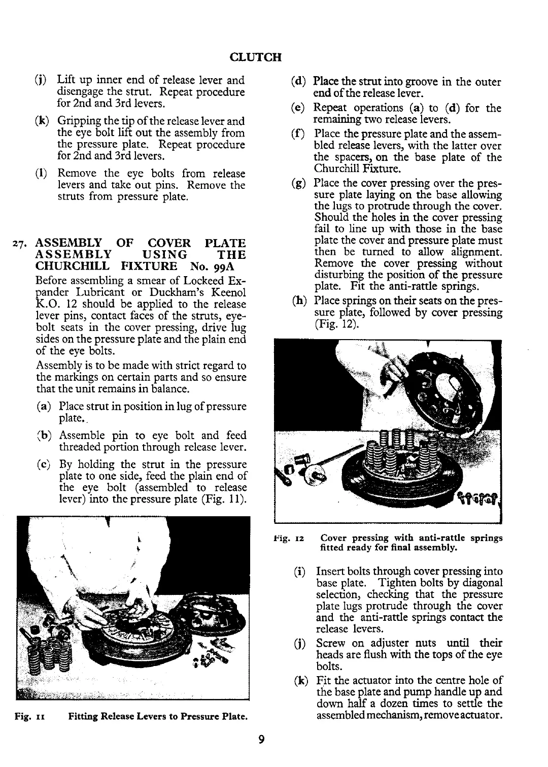
(h)
Place springs on their seats on the pres-
sure plate, followed by cover pressing
(Fig. 12).
Fig.
12
(9
Cover pressing with anti-rattle springs
fitted ready for final assembly.
Insert bolts through cover pressing into
base plate. Tighten bolts by diagonal
selection, checking that the pressure
plate lugs protrude through the cover
and the anti-rattle springs contact the
release levers.
Screw on adjuster nuts
until
their
heads are flush with the tops of the eye
bolts.
Fit the actuator into the centre hole of
the base plate and pump handle up and
down half a dozen times to settle the
assembled mechanism, remove actuator.