CLUTCH
(1)
Secure pillar firmly into centre of base
plate. Place on No.
7
adapter, recessed
side downward, followed by gauge
finger.
(m)
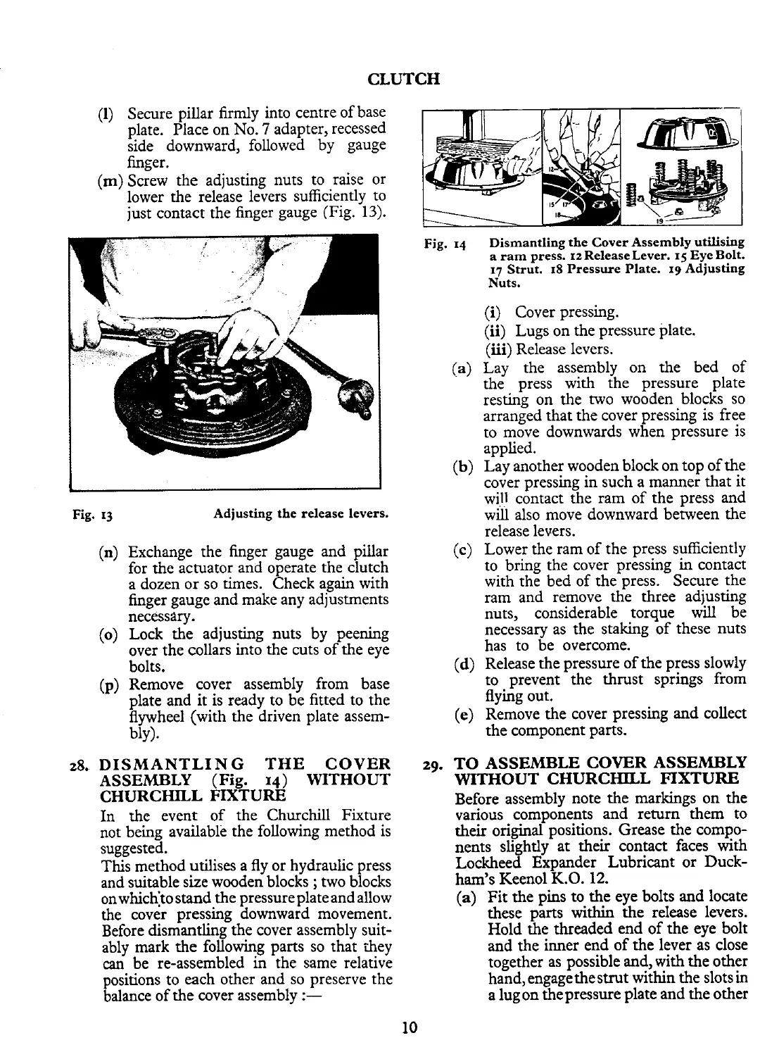
Screw the adjusting nuts to raise or
lower the release levers sufficiently to
just contact the finger gauge (Fig. 13).
Fig.
13
Adjusting the release levers.
(n)
Exchange the finger gauge and pillar
for the actuator and operate the clutch
a dozen or so times. Check again with
finger gauge and make any adjustments
necessary.
(0)
Lock the adjusting nuts by peening
over the collars into the cuts of the eye
bolts.
(p)
Remove cover assembly from base
plate and it is ready to be fitted to the
flywheel (with the driven plate assem-
bly).
28.
DISMANTLING THE COVER
ASSEMBLY
(Fig.
14)
WITHOUT
CHURCHILL FIXTURE
In
the event of the Churchill Fixture
not being available the following method is
suggested.
This method utilises a fly or hydraulic press
and suitable size wooden blocks
;
two blocks
onwhich:to stand the pressure plate and allow
the cover pressing downward movement.
Before dismantling the cover assembly suit-
ably mark the following parts so that they
can
be re-assembled in the same relative
positions to each other and so preserve the
balance of the cover assembly
:-
Fig.
14
Dismantling the Cover Assembly utilising
a
ram Dress.
12
ReleaseLever.
I<
Eve Bolt.
--
-
---
I,
~trti
18 Pressure Plate. xgd~djusting
Nuts.
(i)
Cover pressing.
(ii) Lugs on the pressure plate.
(iii) Release levers.
(a)
Lay the assembly on the bed of
the press with the pressure plate
resting on the two wooden blocks so
arranged that the cover pressing is free
to move downwards when pressure is
applied.
(b)
Lay another wooden block on top of the
cover pressing in such a manner that it
will contact the ram of the press and
will also move downward between the
release levers.
(c)
Lower the ram of the press sufficiently
to bring the cover pressing in contact
with the bed of the press. Secure the
ram and remove the three adjusting
nuts, considerable torque will be
necessary as the staking of these nuts
has to be overcome.
(d)
Release the pressure of the press slowly
to prevent the thrust springs from
flying out.
(e) Remove the cover pressing and collect
the component parts.
29.
TO ASSEMBLE COVER ASSEMBLY
WITHOUT CHURCHILL FIXTURE
Before assembly note the markings on the
various components and return them to
their original positions. Grease the compo-
nents slightly at their contact faces with
Lockheed Expander Lubricant or Duck-
ham's Keen01
K.O.
12.
(a)
Fit the pins to the eye bolts and locate
these parts
within
the release levers.
Hold the threaded end of the eye bolt
and the inner end of the lever as close
together as possible and, with the other
hand, engage
thestrut within the slots
in
a lug on the pressure plate and the other
 Loading...


