CLUTCH
end of the strut push outwards to the
periphery of the pressure plate.
Offer
up the lever assembly,first engaging the
eye bolt shank within the hole in the
pressure plate, then locate the
strut in
the groove of the release lever. Fit the
remaining levers
in
a similar manner.
(b) Place the pressure plate on the wooden
blocks on the base of the press and posi-
tion the thrust springs on the bosses on
the pressure plate.
(c) Place the cover pressing, with the
anti-
rattle springs fitted, over the pressure
plate ensuring that the lugs protrude
through the cover slots.
(d) Arrange a wooden block across the
cover and apply pressure to compress
the whole assembly. Screw the adjust-
ing nuts on to the eye bolts sufficiently
so that pressure can be released.
30.
INSPECTION
OF
COVER
ASSEMBLY
Before re-assembling the clutch
unit
the
parts should be cleaned and inspected. Any
components which show considerable wear
on its working surface should be replaced.
The thrust springs and anti-rattle springs
should be checked against new ones of the
correct strength, and any found to be
obviously weak should be replaced.
The
anti-rattle springs should be assembled to
the cover pressing. The working face of the
cast iron pressure plate should also be
inspected and if the ground face is deeply
scored or grooved it should be either re-
ground or replaced by a new plate.
If any parts are changed or a new pressure
plate fitted, it is essential it should be
static-
ally balanced.
71.
AD.JUSTING
THE
RELEASE LEVERS
-
In service, the original adjustments made by
the clutch manufacturer,
will
require no
attention and re-adjustment is only neces-
sary
if
the cover assembly has been
dis-
mantled.
There are three methods bv which the
release levers may be adjusted.'
(i)
Churchill No. 99A Clutch Fixture.
(ii)
Borg and Beck No. CG 192 gauge
plate. (If available).
(iii)
In the absence of the above the
DrivenPlate Assembly may beused.
(a) Churchill No. ggA Clutch
Fixture.
Both this Company and the Clutch
manufacturers recommend this method.
Details can be found on page 9.
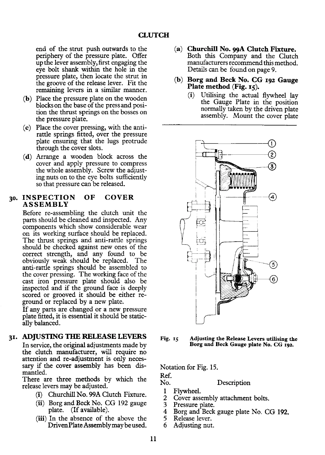
(b) Borg and Beck No. CG
192
Gauge
Plate method (Fig.
15).
(i)
Utilising the actual flywheel lay
the Gauge Plate in the position
normally taken by the driven plate
assembly. Mount the cover plate
Fig.
15
Adjusting the Release Levers utilising the
Borg and
Beck
Gauge plate No. CG
192.
Notation for Fig. 15.
Ref.
No. Description
1 Flywheel.
2 Cover assembly attachment bolts.
3
Pressure plate.
4
Borg and Beck gauge plate No. CG
192.
5
Release lever.
6
Adjusting nut.
 Loading...


