GEARBOX
(h)
Disconnect the two wires from their
terminals on the solenoid
if
an Over-
drive is fitted.
(i)
Remove gearbox mounting &er the
withdrawal of two nuts by jacking up
the
unit,using a block of wood between
jack and sump to avoid damage.
(j)
Remove starter motor bolts and slide
starter motor forwards clear of the bell
housing.
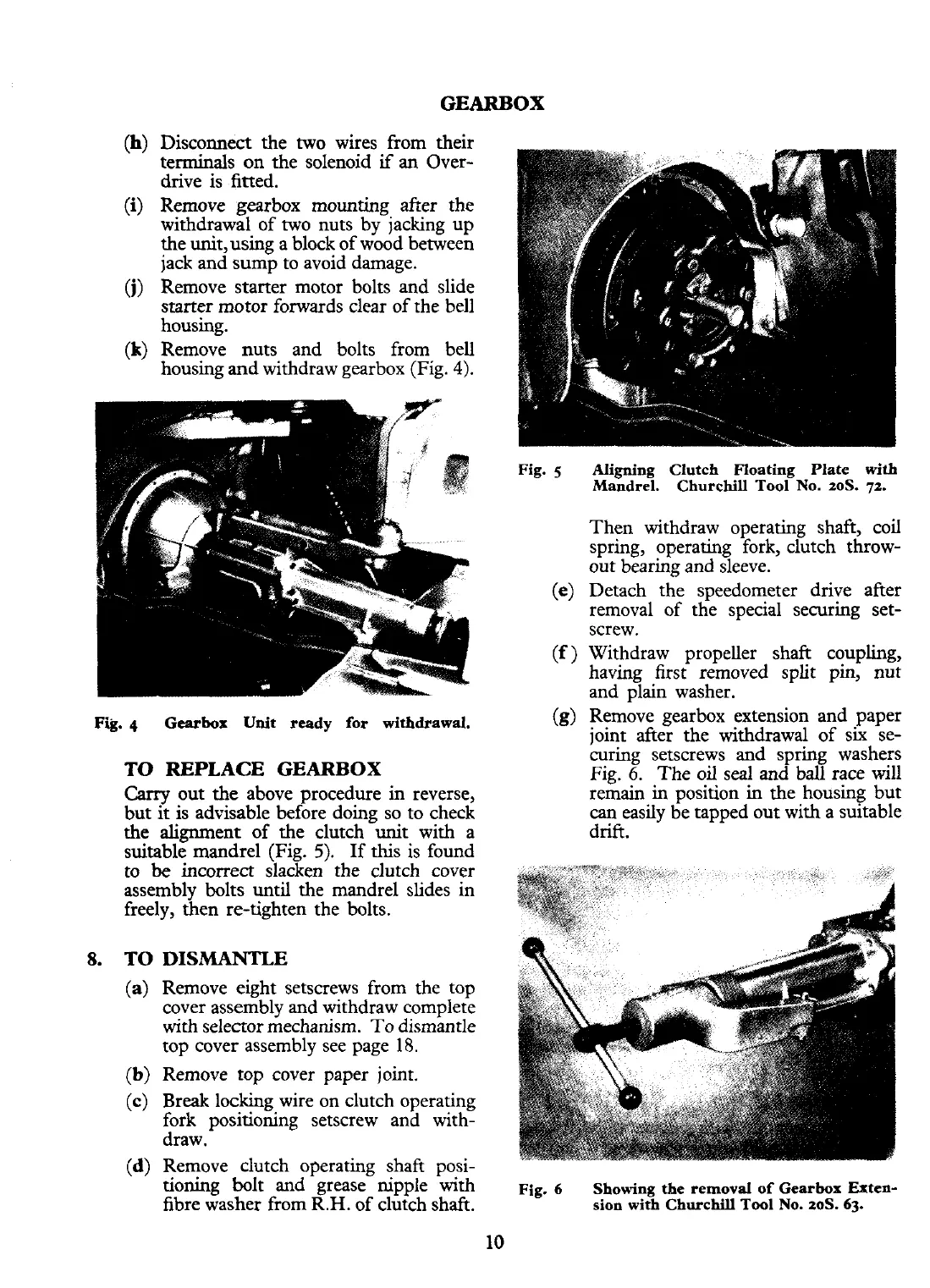
(k)
Remove nuts and bolts from bell
housing and withdraw gearbox (Fig.
4).
Fig.
5
Aligning Clutch Floating Plate with
Mandrel. Churchill Tool No. toS.
72.
Then withdraw operating shaft, coil
spring, operating fork, clutch throw-
out bearing and sleeve.
(e)
Detach the speedometer drive after
removal of the special securing set-
screw.
(f
)
Withdraw propeller shaft coupling,
having first removed split pin, nut
and plain washer.
Fig.
4
Gearbox
Unit
ready for withdrawal.
TO REPLACE GEARBOX
Carry
out the above procedure in reverse,
but
it
is advisable before doing so to check
the alignment of the clutch unit with a
suitable mandrel (Fig.
5).
If this is found
to
be
incorrect slacken the clutch cover
assembly bolts
until
the mandrel slides in
freely, then re-tighten the bolts.
TO
DISMANTLE
(a)
Remove eight setscrews from the top
cover assembly and withdraw complete
with
selector mechanism. To dismantle
top cover assembly see page 18.
(b)
Remove top cover paper joint.
(c)
Break
locking wire on clutch operating
fork positioning setscrew and with-
draw.
(d)
Remove clutch operating shaft posi-
(g)
Remove gearbox extension and paper
joint after the withdrawal of six se-
&ring setscrews and spring washers
Fie.
6.
The oil seal and
ball
race will
re&ain in position in the housing but
can
easily be tapped out with a suitable
drift.
tioning bolt and -grease- nipple -with
Fig.
6
Showing
the
removal of Gearbox Exten-
fibre washer from
R.H.
of clutch shaft.
sion
with
Churchill Tool No.
20s.
63.