GEARBOX
(h)
Withdraw the countershaft locating
in the setscrew heads and withdrawing
setscrew as shown in Fig.
7.
them complete with their plain washers
and lead linger.
Fig.
7
0)
-
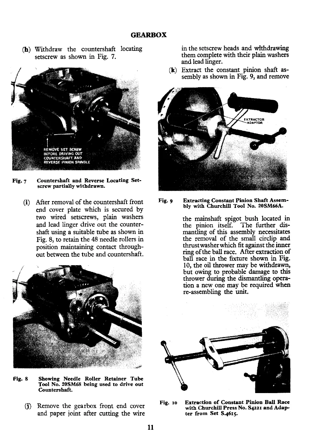
(k)
Extract the constant pinion shaft as-
sembly as shown in Fig.
9,
and remove
Countershaft and Reverse Locating Set-
screw partially withdrawn.
After removal
of
the countershaft
front
Fig.
9
Extracting Constant Pinion Shaft Assem-
end cover plate which is secured by
bly with Churchill Tool No. 20SM66A.
two wired setscrews, plain washers
and lead linger drive out the counter-
shaft using a suitable tube as shown in
Fig. 8, to retain the 48 needle rollers
in
position maintaining contact through-
out between the tube and countershaft.
Fig.
8
Showing Needle Roller Retainer Tube
Tool No. 20SM68 being used to drive out
Countershaft.
the mainshaft spigot bush located
in
the pinion itself. The further dis-
mantling of this assembl necessitates
the removal of the smd circlip and
thrustwasher which
fit
against the inner
ring of the ball race. After extraction of
ball race in the fixture shown
in
Fig.
10, the oil thrower may be withdrawn,
but owing to probable damage to this
thrower during the dismantling opera-
tion a new one may be required
when
re-assembling the unit.
Fig.
10
Extraction
of
Constant Pinion
Ball
Race
(j)
Remove the gearbox front end cover
with
Churchill Press No. S~ZI and Adap
and paper joint after cutting the wire
ter from Set S.4615.