GEARBOX
this position with the corrrct thrust
washer fitted, the small seeger circlip
fits properly into its recess. When
passing this circlip along the ground
portion of the constant pinion shaft,
take care not to score the shaft as such
damage may cause subsequent leakage
of oil. Fit larger
drclip into the amdar
groove
in
the outer ring of the ball
race.
(k)
Fit Oilite spigot bush into constant
pinion, placing the internally bevelled
portion of it towards the mainshaft.
(1)
Drive the constant pinion shaft and
bearing into the gearbox casing, posi-
tioning the gap in the circlip on the
outer ring of the bearing in
line
with
the oil hole
in
the casing.
Utilising a feeler gauge, measure the
distance between the dog teeth of all
the mainshaft synchro gears, and the
dog teeth of their respective baulk
rings. (Fig. 23).
Fig. 23 Measuring the gap between Baulk Ring
teeth
and
Cone.
Move the outer synchro sleeve towards
the gear being measured. thus forcing
the
baulking ring on to its cone. In this
position the dimension should be
between
.035"
and
.040n
for new com-
ponents and
.005"
to
.010"
less for
components which have been run-in.
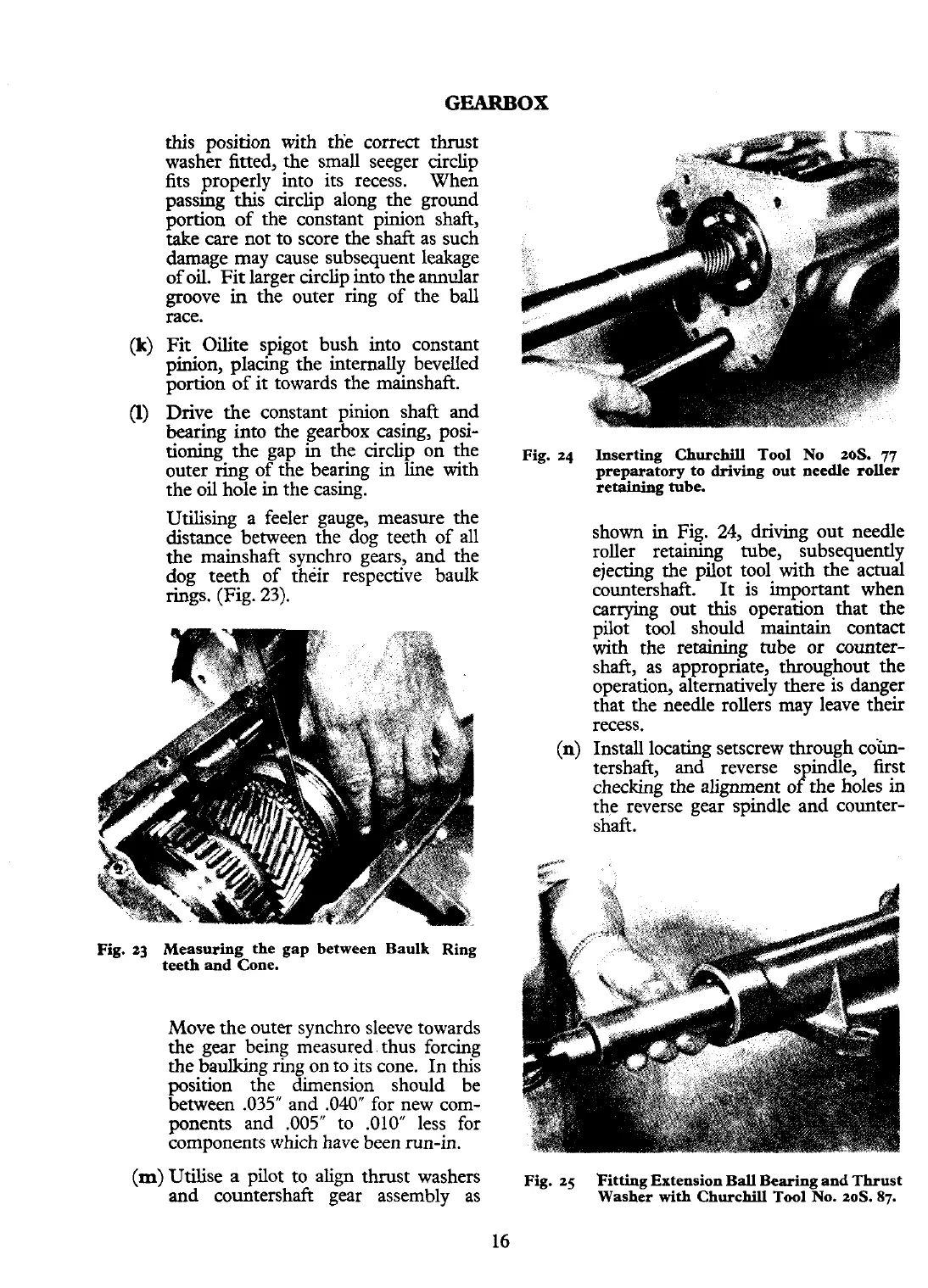
Fig.
24
Inserting
Churchill
Tool No 20s.
77
preparatory to driving out needle roller
retaining tube.
shown in Fig. 24, driving out needle
roller retaining tube, subsequently
ejecting the pilot tool
with
the actual
countershaft. It is important when
carrying out this operation that the
pilot tool should
maintain
contact
with the retaining tube or counter-
shaft, as appropriate, throughout the
operation, alternatively there is danger
that the needle rollers may leave their
recess.
(n)
Install locating setscrew through cob
tershaft, and reverse spindle, first
checking the alignment of the holes in
the reverse gear spindle and counter-
shaft.
(m)
Utilise a pilot to align thrust washers
Fig. 25
Fitting Extension Ball Bearing and Thrust
and countershaft gear assembly as
Washer
with
Churchill
Tool
NO.
20s.
87.
16