GEARBOX
(iv)
Axial
release loading of 2nd speed
synchro unit 25-27 lbs.
(v)
Axial
release loading of 3rd and
top speed synchro unit 19-21
lbs.
(iv)
and
(v)
can be checked as shown
in Fig. 20. If it is found to be in-
Fig.
2q
(9
TO
SPRING
BALANCE
Fixture which
can
be
readily
manu-
factured to test Synchro Axial loading.
correct, steel shims
can
be added or
removed from below the axial re-
lease loading springs to increase or
decrease respectively the axial release
load as required.
After completion of checks the
main-
shaft circlip, thrust washers and con-
stant gear bushes can be removed.
The mainshaft
can
then be installed
into the gearbox casing, and assembled
as follows
:
(i)
Second speed synchro unit in-
corporating the first mainshaft
gm.
(ii)
Thrust
washer
with
three lugs to
fit splines.
(iii)
Second mainshaft constant gear
and bush.
(iv)
Third mainshaft constant gear,
bush and thrust washer fitted
with
oil scroll towards gear.
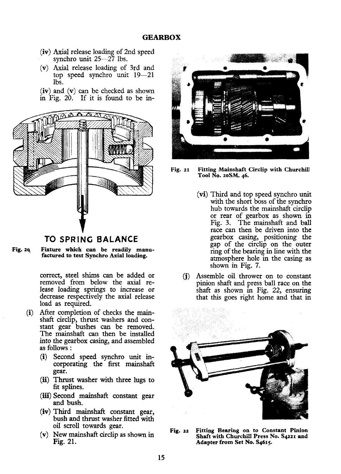
(v)
New mainshaft circlip as shown in
Fig. 21.
Fig.
21
Fitting Mainshaft Circlip with Churchill
Tool No. zoSM. 46.
(vi)
Third and top speed synchro unit
with the short boss of the synchro
hub towards the mainshaft circlip
or rear of gearbox as shown in
Fig. 3. The
mainshaft and ball
race can then be driven into the
gearbox casing, positioning the
gap of the circlip on the outer
ring of the bearing in line with the
atmosphere hole in the casing as
shown in Fig.
7.
(j)
Assemble oil thrower on to
constant
pinion shaft and press ball race on the
shaft as shown in Fig. 22, ensuring
that this goes right home and that in
Fig.
22
Fitting Bearing on to Constant Pinion
Shaft
with
Churchill Press No.
Sqtzr
and
Adapter
from
Set No. S4615