GEARBOX
INSTALLATION OF OVERDRIVE
I.
DIShUNTLING
the distance piece and finally the con-
stant speed gear
with
the boss towards
Remove the detachable floor pressing from
the distance piece.
around the gearbox. Remove the four bolts
(f
)
Position the
completed countershaft
connecting the propeller shaft to the
gear-
gear assembly in the bottom of the
box flange. Disconnect the speedometer
gear case and slide into position the
drive from the gearbox. Remove the rear thrust washer.
bottom nuts of rear mounting and jack up
engine sufficiently to allow removal of rear
(g)
For checking purposes the counter-
mounting. Remove the starter motor.
shaft should be fitted.
The counter-
Remove the clevis pin from the lever on
shaft gears (when new) have
an
end
the clutch operating shaft.
float of
.006"-.010".
(h)
After checking,the countershaft should
Remove the bolts from around the bell
be removed by pushing the needle re-
housing and detach the gearbox from the taining tube into the countershaft
engine.
gears and forcing the
layshaft out, after
The gearbox should now be dismantled and
which the gears will drop to the
the various gears and ball races examined
bottom of the gearbox casing.
for possible damage. Any parts which are
(i)
Fit the triangular washer, ball race,
damaged or suspect
in
any way should be distance washer and circlip to the new
replaced. mainshaft. Gripping the mainshaft
The mainshaft originally fitted will be re-
in the protected jaws of a vice,
placed by the special one supplied. To
assemble the gears on this shaft up to
ensure the future life of the Overdrive Unit
the main locating circlip, ensuring that
it is advisable to fit a new mainshaft
bear-
the recess for this is free for its
ing.
eventual entry by checking with half
the circlip previously used (a new one
2.
ASSEMBLY OF GEARBOX
will be required when re-assembling).
When a new 2nd or 3rd mainshaft gear
Proceed to re-assemble in the following
is to be fitted, ensure that
.004"-.006"
manner after ensuring that the gearbox has
end float of the gears is permitted by
been drilled as shown in Fig. 31.
the length of their bushes, when in
their fitted position.
(a)
Fit 1st and reverse idler pinion and
shaft with the smaller gear pointing
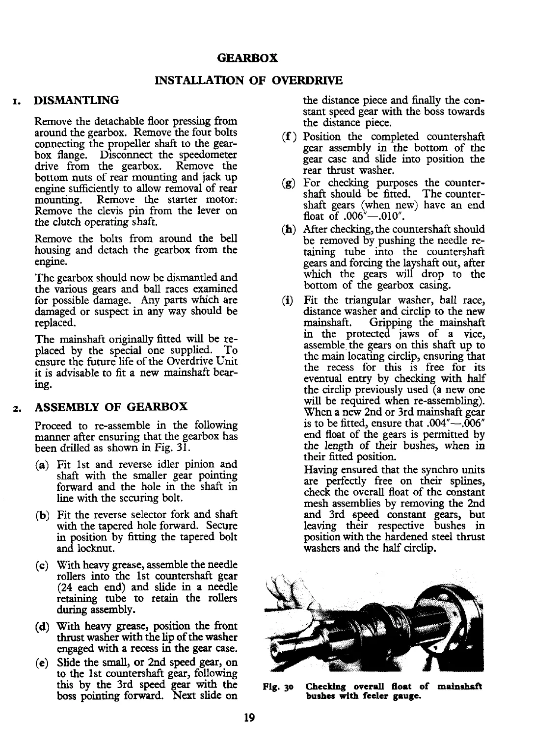
Having ensured that the synchro units
forward and the hole in the shaft in
are perfectly free on
their splines,
line with the securing bolt.
check the overall float of the constant
mesh assemblies by removing the 2nd
(b)
Fit the reverse selector fork and shaft
and 3rd speed constant gears, but
with the tapered hole forward. Secure leaving their respective bushes in
"d"
sition by fitting the tapered bolt
position
with
the hardened steel thrust
an locknut. washers and the half circlip.
(c) With heavy grease, assemble the needle
rollers into the 1st countershaft gear
(24
each end) and slide in a needle
retaining
tube
to retain the rollers
during assembly.
(d)
With heavy grease, position the front
thrust washer
with
the
lip
of the washer
engaged with a recess in the gear case.
(e)
Slide the small, or 2nd speed gear,.on
to the 1st countershaft gear, followmg
this by the 3rd speed gear
with
the
~ig.
jo
chec~lng
orera float of
rnPinshrft
boss pointing forward.
Next
slide on
bushes
with
feeler gauge.
19
 Loading...


