GEARBOX
The end float can then be checked with
a
set of feeler gauges as shown in
Fig.
30.
The correct float should be
between .007" and .012".
Remove the mainshaft details remain-
ing on the shaft and begin the final
assembly.
Feed the shaft into the casing and
assemble the 2nd gear synchro unit,
the hardened steel thrust washer which
must be located on the
splines, the 2nd
constant gear with its bush, the 3rd
constant gear with bush, the front
hardened steel thrust washer and finally
fit the main locating circlip with a
special sleeved tool.
Withdraw the gearbox mainshaft,
with
the gears so far assembled, sufficiently
towards the rear to enable the assembly
to be tipped upwards, thus permitting
the 3rd and top synchro unit to be
fitted.
Tap the mainshaft assembly into
position and fit the constant pinion
assembly.
--A
Fig.
31
Showing the oil transfer hole and method
of wiring bolts. The Gearbox casing has
to be drilled on early models whereas
d
present production are already drilled.
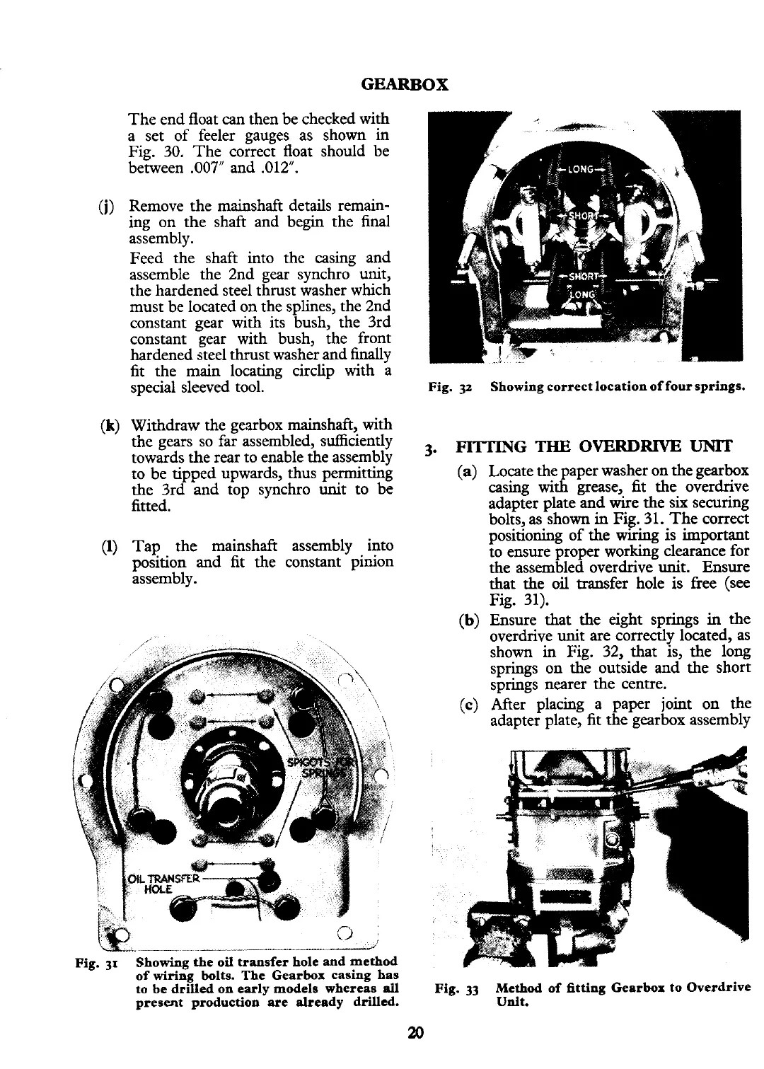
Fig.
32
Showing correct location of four springs.
3.
FITTING
THE
OVERDRIVE
UNIT
(a)
Locate the paper washer on the gearbox
casing
with
grease,
fit
the overdrive
adapter plate and wire the six securing
bolts, as shown
in
Fig. 31. The correct
positioning of the wiring is important
to ensure proper working clearance for
the assembled overdrive unit. Ensure
that the
oil
transfer hole is free (see
Fig. 31).
(b)
Ensure that the eight springs
in
the
overdrive unit are correctly located, as
shown in Fig. 32, that 'Is, the long
springs on the outside and the short
springs nearer the centre.
(c)
After placing a paper joint on the
adapter plate, fit the gearbox assembly
Fig.
33
Method of fitting Gearbox to Overdrive
Udt.