GEARBOX
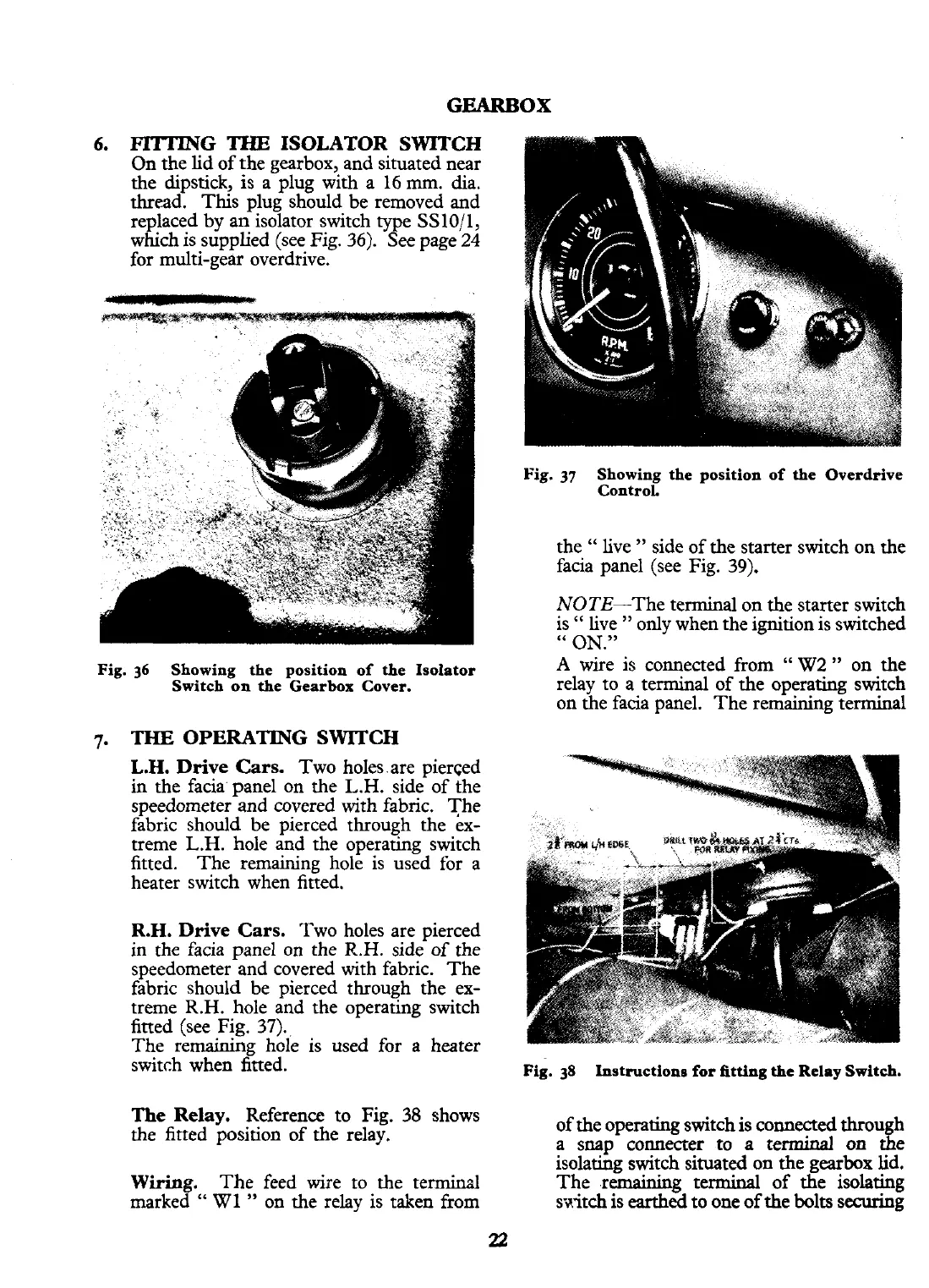
6.
THE
ISOLATOR SWITCH
On the lid of the gearbox, and situated near
the dipstick, is a plug with a
16
mm.
dia.
thread. This plug should be removed and
replaced by an isolator switch type SS10/1,
which is supplied (see Fig.
36).
See page
24
for multi-gear overdrive.
Fig.
37
Showing the position of the Overdrive
ControL
the
"
live
"
side of the starter switch on the
facia panel (see Fig. 39).
NOTE-The terminal on the starter switch
is
"
live
"
only when the ignition is switched
"
ON."
Fig.
36
Showing the position of the Isolator
Switch on the Gearbox Cover.
THE
OPERATING SWlTCH
L.H.
Drive Cars.
Two holes,are pierced
in
the facia' panel on the L.H. side of the
speedometer and covered with fabric. The
fabric should be pierced through the ex-
treme L.H. hole and the operating switch
fitted. The remaining hole is used for a
heater switch when fitted.
R.H.
Drive Cars.
Two holes are pierced
in the facia panel on the
R.H.
side of the
speedometer and covered with fabric. The
fabric should be pierced through the ex-
treme R.H. hole and the operating switch
fitted (see Fig. 37).
The remaining hole is used for a heater
switch when fitted.
The Relay.
Reference to Fig.
38
shows
the fitted position of the relay.
Wiring.
The feed wire to the terminal
marked
"
W1
"
on the relay is taken from
A
wire is connected from
"
W2
"
on the
relay to a terminal of the operating switch
on the facia panel. The remaining terminal
Fig.
38
Instructions for fitting the
Relay
Switch.
of the operating switch is connected through
a snap connecter to
a
terminal on
the
isolating switch situated on the
gearbox
lid.
The remaining terminal of the isolating
switch is earthed to one of the
bolts
securing