GEARBOX
10
STARTER
50L
5WITCt-l
WHITE
FEED
SIDE.
OPERATING
ISOLATOR.
SWITCH.
SWITCH
RELAY CONTACTS
y971
TO
AMMETER
-L
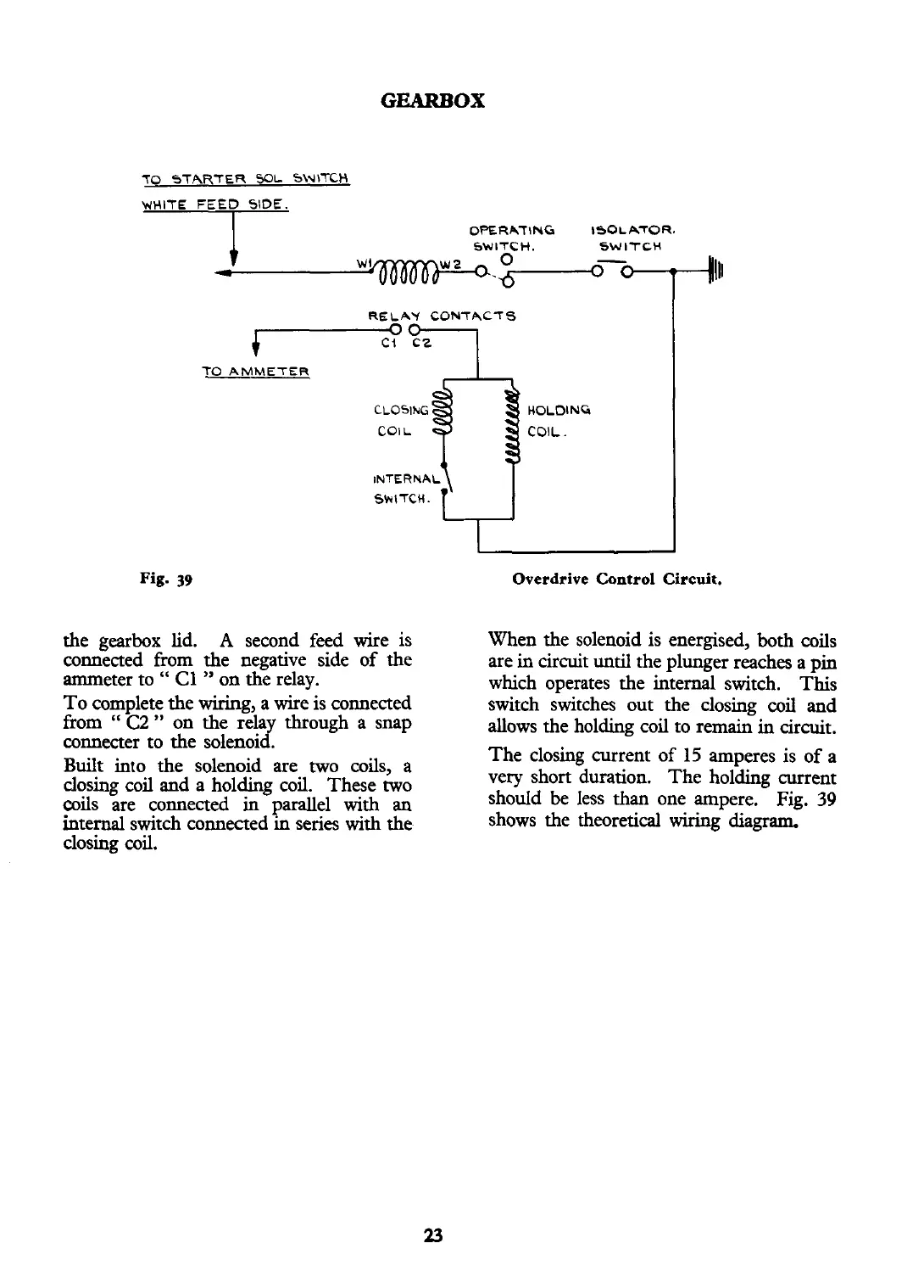
the gearbox lid.
A
sewnd feed wire is
connected from the negative side of the
ammeter to
"
C1
"
on the relay.
To complete the wiring, a wire is connected
from
"
C2
"
on the relay through a snap
connecter to the solenoid.
Built into the solenoid are two coils, a
closing coil and a holding coil.
These two
coils are connected in parallel with an
internal switch connected in series with the
closing wil.
Overdrive Control Circuit.
When the solenoid is energised, both coils
are in circuit
until
the plunger reaches a pin
which operates the internal switch.
This
switch switches out the closing ail and
allows the holding coil to remain in circuit.
The closing current of
15
amperes is of a
very short duration. The holding current
should be less
than
one ampere. Fig.
39
shows the theoretical wiring diagram.