REAR
AXLE
9.
TO
REPLACE
THE
AXLE
If a replacement axle is being fitted it will
be necessary to remove the complete brake
assemblies at the axle ends.
It is not necessary to remove the hubs,
for these
can
be removed with the half
shafts and brake backing plates.
The axle must be tilted during the fitting
operations and filling the axle with oil
should be delayed until the axle has been
fitted to the car.
The fitting is the reversal of the removal.
For the bleeding of the hydraulic system
see
"
Brakes-Section R."
10.
TO
DISMANTLE
the axle is going to be completely
dismantled the hubs
can
be removed at
a later stage, which means that the
half shafts, hubs, brake backing plates,
etc., must be removed as an assembly.
(d)
Remove brake shoes and return springs.
(e)
Withdraw the brake backing plates
after removal of the eight bolts, spring
washers and nyloc nuts, four from
either back plate. Further dismantling
of the brake
backing plates only require
the removal of the hydraulic wheel
cylinders and anchor blocks, the latter
being secured by spring washers and
two nuts, the former
can
be withdrawn
provided the hydraulic connections,
rubber dust sealing boots, etc., have
-
Drain oil. been removed.
Remove wheel securing cones (wire
(f)
The half shafts
can
now be withdrawn
wheel hubs only).
This enables the
from the axle
casing,the bearing hous-
brake drum securing screws to be
ings tapped off the bearings and the
removed and the drums withdrawn. bearines withdrawn with a suitable
"
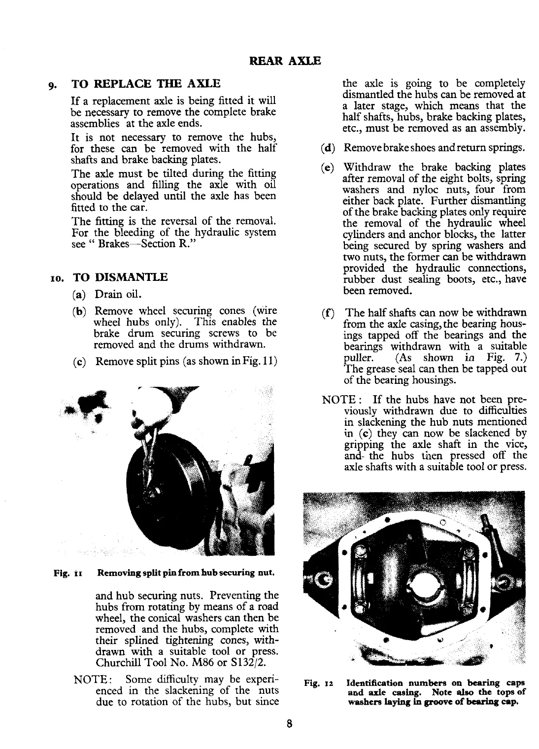
Remove split pins (as shown in Fig. 11) puller. (As shown in Fig.
7.)
The grease seal can then be tapped out
of the bearing housincs.
Fig.
ir
Removing split pin from hub securing nut.
and hub securing nuts. Preventing the
hubs from rotating by means of a road
wheel, the conical washers can then be
removed and the hubs, complete with
their
splined tightening cones, with-
drawn with a suitable tool or press.
Churchill Tool No.
M86
or S132/2.
NOTE:
Some difficulty may be experi-
enced
in
the slackening of the nuts
due to rotation of the hubs, but since
NOTE
:
If the hubs have not been pre-
viously withdrawn due to difficulties
in slackening the hub nuts mentioned
in
(c)
they can now be slackened by
gripping the axle shaft in the vice,
and- the hubs then pressed off the
axle shafts with a suitable tool or press.
Fig.
12
Identification numbers on
bearing
caps
and
axle
casing.
Note
also
the tops of
washers
laying
in
groove
of
beprlns
cap.
 Loading...


