REAR
AXLE
Remove axle centre casing cover and
joint after withdrawal of eight setscrews.
K
4
Remove the differential bearing caps,
n
notinnthe markings stamped on the tor,
of these and the c&resp&dingly abuG-
ing portions of the casing. The existing
relation between the caps and casing
must be retained when re-assembling.
Fig. 12 shows example of markings.
Apply axle casing spreader as shown
in Fig.
13,
and
lift
differential assembly
Fig. 13 Casing spreader
in
position.
Churchill
Tool
No. SIOI.
out of the axle centre casing.
"
Spread-
ing
"
should be limited to that required
to just free the assembly
in
the casing.
Suitably identify the respective outer
portion of the differential bearings
with their inner races. The inter-
relation of the component parts of
these races must be retained when
re-assembling the rear axle.
(k)
Remove the crown wheel from its
mounting flange after the withdrawal
of the ten fixing bolts, leaving further
dismantling of the differential unit
until a later stage.
(1)
After removal of split pinned flange
nut as shown in Fig. 14, and having
removed the flange, drive the pinion
out through the casing with a hide
faced hammer. Lay aside the shims
which are
fitted
between
the spacer
Fig.
14
Removing split pin from driving flange
securing nut.
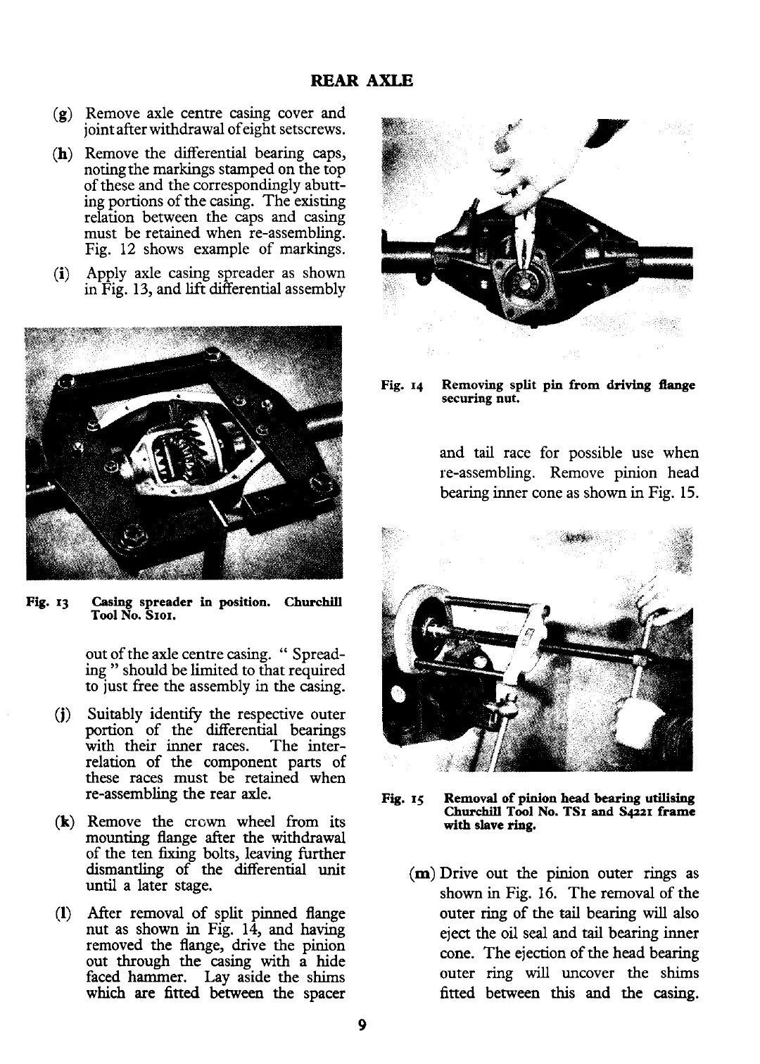
and tail race for possible use when
re-assembling. Remove pinion head
bearing inner cone as shown in Fig. 15.
Fig.
15
Removal of pinion
head
bearing
utilising
Churchill
Tool No. TSI
and
Sqzzr frame
with
slave
ring.
(m)
Drive out the pinion outer rings as
shown in Fig.
16.
The removal of the
outer
ring
of the
&
bearing
will
also
eject the oil seal and
tail
bearing inner
cone. The ejection of the head bearing
outer ring
will
uncover the shims
fitted between
this
and the casing.