REAR
AXLE
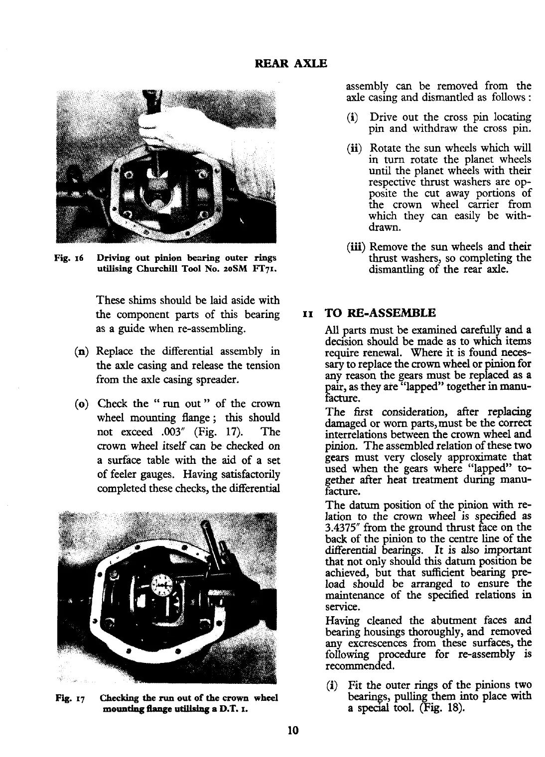
Driving
out pinion
bearing
outer
rings
utilising
Churchill
Tool
No.
zoSM
FT71.
These shims should be laid aside with
the component parts of this bearing
as a guide when re-assembling.
Replace the differential assembly in
the axle casing and release the tension
from the axle casing spreader.
Check the
"
run
out" of the crown
wheel mounting flange; this should
not exceed
.003"
(Fig.
17).
The
crown wheel itself
can
be
checked on
a surface table with the aid of a set
of feeler gauges. Having satisfactorily
completed these checks, the differential
Fig.
17
Checking
the
run
out of
the
crown
wheel
mouutkrg
we
utilkhg
a
D.T.
I.
assembly
can
be removed from the
axle casing and dismantled as follows
:
(i)
Drive out the cross pin locating
pin and withdraw the cross pin.
(ii)
Rotate the sun wheels which will
in turn rotate the planet wheels
until the planet wheels with their
respective
thrust washers are op-
posite the cut away portions of
the crown wheel carrier from
which they
can
easily be with-
drawn.
(iii)
Remove the sun wheels and their
thrust washers, so completing the
dismantling of the rear axle.
TO
RE-ASSEMBLE
All
parts must be examined carefully and a
decision should be made as to which items
require renewal. Where
it
is found neces-
sary to replace the crown wheel or pinion for
any reason the gears must be replaced as a
pair, as they
afe "lapped" together in manu-
facture.
The first consideration, after replacing
damaged or worn parts, must be the correct
interrelations between the crown wheel and
pinion. The assembled relation of these two
gears must very closely approximate that
used when the gears where "lapped" to-
gether after heat treatment during manu-
facture.
The
datum
position of the pinion with re-
lation to the crown wheel is specified as
3.4375" from the ground thrust face on the
back of the pinion to the centre line of the
differential bearings. It is also important
that not only should this datum position be
achieved, but that sufficient bearing pre-
load should be arranged to ensure the
maintenance of the specified relations in
service.
Having cleaned the abutment faces and
bearing housings thoroughly, and removed
any excrescences from these surfaces, the
following procedure for re-assembly is
recommended.
(i)
Fit the outer rings of the pinions two
bearings, pulling them into place
with
a
special
tool.
(Fig.
18).