REAR
Although the packing shims are sup-
plied to nominal thicknesses, the dimen-
sions should be measured with a
micrometer gauge. It is important that
no damaged shims are used and that
they are thoroughly cleaned before
measurement. (Fig. 21.)
Remove the pinion setting gauge,
dummy pinion and pinion bearing
outer rings.
Insert the measured pack of shims on
the pinion head bearing outer ring
abutment face (Fig. 22) and replace
the pinion bearing outer rings, pulling
them into place with the special tool
shown
in
Fig. 18.
Fig.
22
(vii)
(viii)
(h)
Shims placed in position on outer ring
abutment face.
Press the pinion head bearing inner
cone on to the pinion shaft (Fig.
23).
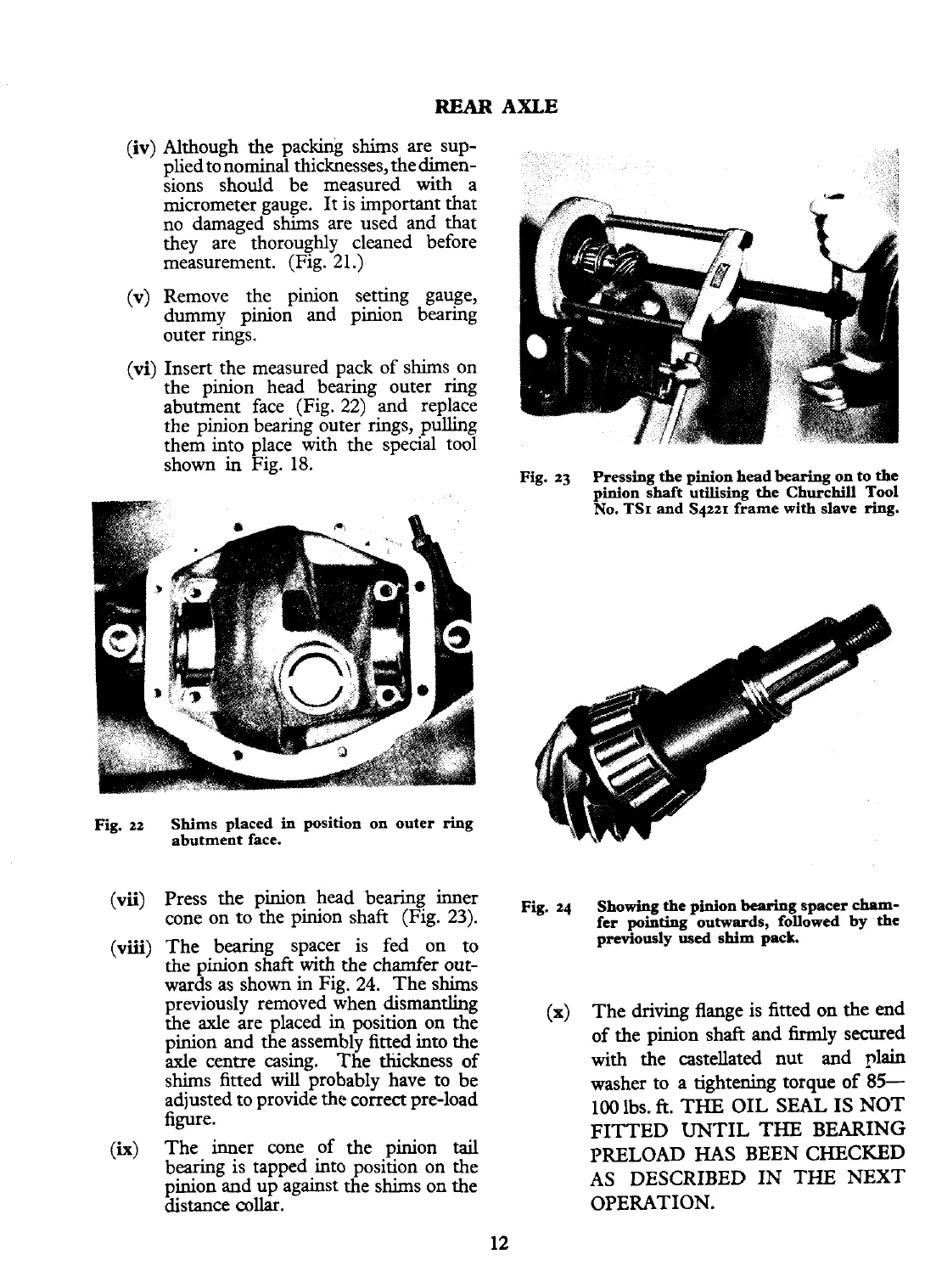
The bearing spacer is fed on to
the pinion shaft with the chamfer out-
wards as shown in Fig. 24. The shims
previously removed when dismantling
the axle are placed
in
position on the
pinion and the assembly fitted into the
axle centre casing. The thickness of
shims fitted
will
probably have to be
adjusted to provide the correct pre-load
figure.
The inner cone of the pinion
tail
bearing is tapped into position on the
pinion and up against the shims on the
distance
collar.
AXLE
Fig.
23
Pressing the pinion head bearing on to the
pinion shaft utilising the Churchill Tool
No.
TSI
and S4221 frame with slave
ring.
Fig.
24
Showing
the
pinion bearing spacer cham-
fer pointing outwards, followed
by
the
previously
used
shim pack.
(X)
The driving flange is fitted on the end
of the pinion shaft and firmly secured
with the castellated nut and plain
washer to a tightening torque
of
85-
100
lbs.
ft.
THE OIL SEAL IS
NOT
FITTED UNTIL THE BEARING
PRELOAD
HAS
BEEN CHECKED
AS DESCRIBED IN THE
NEXT
OPERATION.