REAR
AXLE
Testing the pre-load of the pinion bearing
utilising the Churchill Tool No. 2oSM.
98
Note: The oil seal is not fitted at this
juncture.
The fixture shown in Fig.
25
is now
a~~lied and the
re-load
of the bearings
&cked. The correct pre-load should
fall between
15-18
in. lbs. If the pre-
load is inadequate shims must be with-
drawn, whereas if an excessive figure
is obtained additional shims must be
fined.
When the correct pinion pre-load is
obtained remove driving flange and
fit
the oil seal (Fig.
26),
after which the
Fig. 26
Fitting pinion housing oil seal utilising
Churchill Tool No. Mmo.
flange should be replaced, the castel-
lated nut tightened to the correct
torque and split pinned.
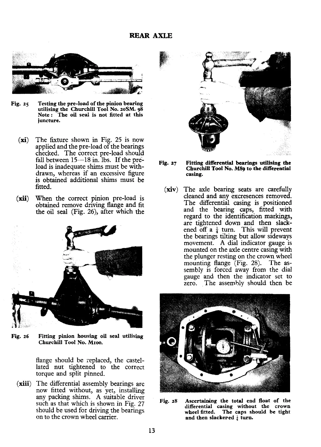
(xiii)
The differential assembly bearings are
now fitted without, as yet, installing
any packing shims.
A
suitable driver
such as that which is shown in Fig.
27
should be used for driving the bearings
on to the crown wheel carrier.
Fig.
27
Fitting Merentid
bearings
utilising the
Churchill
Tool
No.
MSg
to the diierential
casing.
(xiv)
The axle bearing seats are carefully
cleaned and any excresences removed.
The differential casing is positioned
and the bearing caps, fitted with
regard to the identification markings,
are tightened down and then slack-
ened off a
f
turn. This will prevent
the bearings tilting but allow sideways
movement.
A
dial indicator gauge is
mounted on the axle centre cazng\ith
the plunger resting on the crown wheel
mounting flange (Fig.
28).
The as-
sembly is forced away from the dial
gauge and then the indicator set to
zero. The assembly should then be
~i~.
28
Ascertaining the total end float of the
dserential casing without the crown
wheel fitted. The caps should be tight
and then
slacke~ed
$
turn.