REAR
AXLE
levered in the
opposite
direction until
the taper roller bearings go hard home.
The reading on the
dial
gauge (.062"
for example) will indicate the total
side float of the crown wheel carrier
and should be noted for later reference.
(xv)
The crown wheel carrier is now re-
moved from the axle centre casing so
that the sun gears, planet gears and
thrust washers
can
be assembled, the
cross pin being used to locate the two
planet gears with their respeceive thrust
washers temporarily in position (Fig.
29). Subsequently, the planet gears are
Fig.
29
~ocation
of
planet
gears
for entry into the
differential
casing.
rotated round the sun wheel through
90 degrees, the cross pin being
with-
drawn to allow the gears to assume
their normal fitted position, and the
cross pin finally fitted and secured by
its locking pin, this pin being located
by "centre popping."
(xvi)
The crown wheel is fitted to the crown
wheel carrier, the fixing bolts
thoroughly tighten to 22-24 lbs.
ft.
and secured with their respective lock-
ing plates.
NOTE
:
The crown wheel attachment
bolts were increased in diameter from
h''
to
4''
at
rear axle
No.
TS.4731.
The crown wheel
is
checked for flush
fitting against the flanged face of the
carrier with a feeler
gauge,thus ensuring
that the crown wheel goes right home
and also that there
can
be no question
of casting distortion. The maximum
permissible
run
out of the crown wheel
and crown wheel mounting flange
is
.003". The flange
can
be checked
before the fitting of the crown wheel
by rotating it on its bearings, using a
dial
indicator, the crown wheel itself
on a surface table
with
the aid of feeler
gauges.
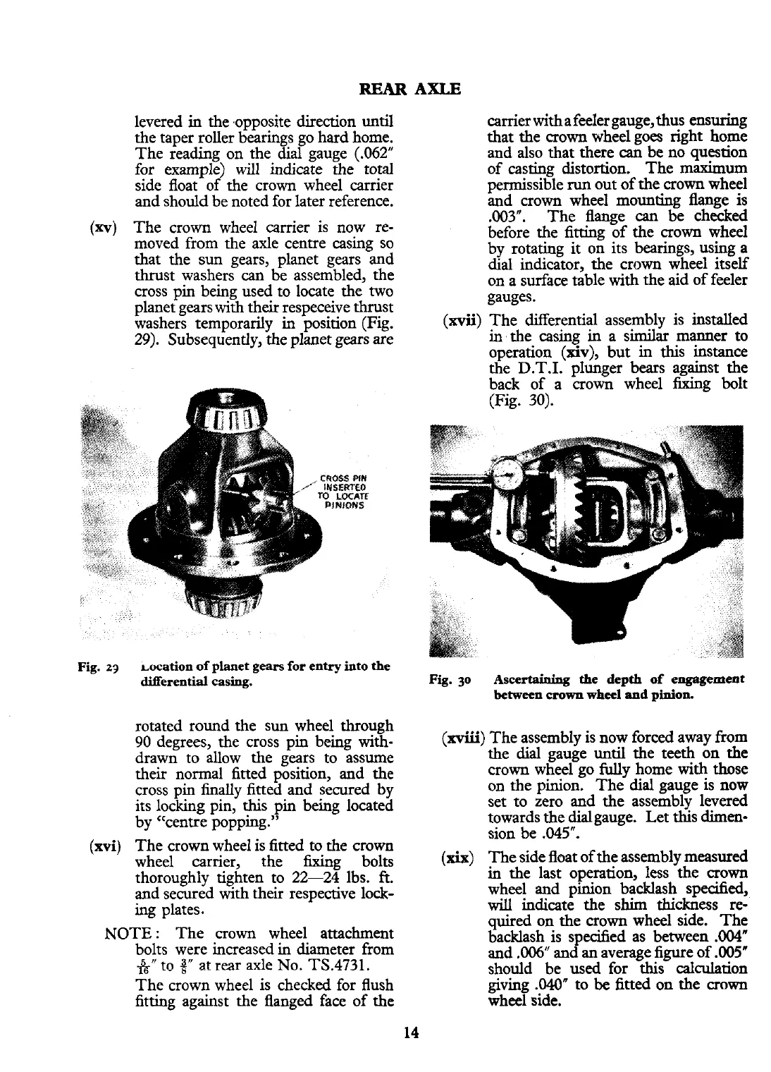
(xvii)
The differential assembly is installed
in'the casing in a similar manner to
operation
(xiv),
but in this instance
the D.T.I. plunger bears against the
back of a crown wheel fixing bolt
(Fig. 30).
Fig.
30
Ascertaining
the depth of
engagement
between
crown
wheel
and
pinion.
(xviii)
The assembly is now forced away from
the dial gauge until the teeth on the
crown wheel go
fully
home with those
on the pinion. The dial gauge is now
set to zero and the assembly levered
towards the dialgauge. Let this
dimen-
sion be
.045".
(xix)
The side float of the assembly measured
in the last operation, less the crown
wheel and pinion backlash specified,
will
indicate the shim thickness re-
quired on the crown wheel side. The
backlash is specified as between
.W"
and .006" and
an
average figure of
.005"
should be used for this calculation
giving
.04OW
to
be
fitted on the crown
wheel side.
 Loading...


