REAR
AXLE
To obtain the thickness of the shims
required between the other differential
bearing and casing, the figure arrived
at in previous operation,
i.e.,
.040",
should be subtracted from the total
side float measured in operation (xiv),
plus an allowance of .005" to provide
the necessary degree of bearing pre-load.
This gives a total shim thickness of
.067" and thus shims on two bearings
will be .040" already estimated and
.067"
-
.040"=.027" on the other side.
Having decided the thickness of shims
required behind each differential bear-
ing, these bearings are extracted with
the special tool shown
in
Fig.
31.
The
Fig. 31
Removal of the differential bearing utilis-
ing the Churchill Tool No. S103 and
Sqsrr
frame.
respective shim packs are measured
with a micrometer gauge after ensuring
that the shims are clean and undamaged
and allocated to their respective sides
of the crown wheel carrier.
(xxii)
As each bearing is extracted, the two
portions of each must be laid aside for
refitting in the same relation and posi-
tion as thatused during initial assembly.
Failure to
fit
these bearings in their
original positions will upset the
measurements made in previous opera-
tions.
(xxiii)
Having fitted the two packs of shims
in their respective positions the bearing
inner cones are driven on to the carrier
with a suitable sleeve tool as shown in
Fig. 27 and the outer rings applied.
(xxiv) The differential assembly is now fitted
into the axle centre casing and, owing
to the pre-loadi& of the bearings, a
certain amount of casing spreading is
desirable to complete this operation.
THE CASING SPREADER
SHOWN IN FIG.
13
SHOULD
BE USED AND THE SPREADING
OF THE CASE LIMITED TO
THAT JUST REQUIRED TO
EN-
ABLE THE DIFFERENTIAL
ASSEMBLY TO ENTER THE
CASING.
(xxv) The bearing caps are then fitted in
their respective positions so that the
number stamped on the caps coincide
with those stamped on the axle casing,
tightenine them to their correct toraue
ofu34-36ulbs. ft.
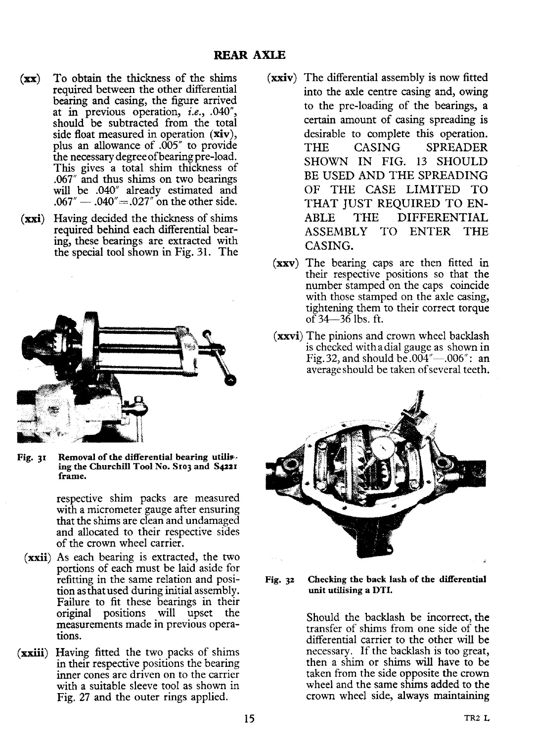
(xxvi) The pinions and crown wheel backlash
is checked withadial gauge as shown in
Fig.
32,
and should be .004"-,006": an
average should be taken ofseveral teeth.
Fig. 32
Checking the back lash of the differential
unit utilising a
DTI.
Should the backlash be incorrect, the
transfer of shims from one side of the
differential carrier to the other will be
necessary.
If
the backlash is too great,
then a shim or shims
will
have to be
taken from the side opposite the crown
wheel and the same shims added to the
crown wheel side, always
maintaining