REAR
AXLE
the same overall total.Should the back-
lash be insufficient, then the reverse
procedure must be adopted.
(xxvii)
A
tooth marking test should now be
carried out, and to enable this to be
done a few teeth should be painted with
a suitable marking compound. The
pinion should be rotated backwards
and forwards by the driving flange,
over the marked teeth on the crown
wheel, and the
markings compared
with the diagram (Fig.
33), and the
instructions on this diagram regarded.
HYPOID CROWN WHEEL
TOOTH
MARKINGS
DRIVE
SIDE
OVERRUN SIDE
CORRECT
MARKINGS
ON
GEAR
4
PINION
CONE
TOO
CLOSE
PINION
CONE
TOO
WIDE
(d)
A
new axle cover packing
is
fitted,
together
with
the cover
itself,
and the
latter secured
with
the eight setscrews.
(xxix)
Drive the wheel
bearings
on to their
respective axle shaft
(Fig.
9),
and
assemble to the axle
unit.
(XSX)
The grease seals should now
be
tapped
into the
bearing
housings
(Fig.
8),
and the assemblies
fitted
to each axle
sleeve, followed by the brake backing
plate
and
shoe assembly.
(xxxi)
The four bolts are fitted through each
bearing
housing and brake baclung
plate, ensuring that both these items
assume
their
appropriate relation with
the axle sleeve, the nuts are screwed
into position and firmly tightened.
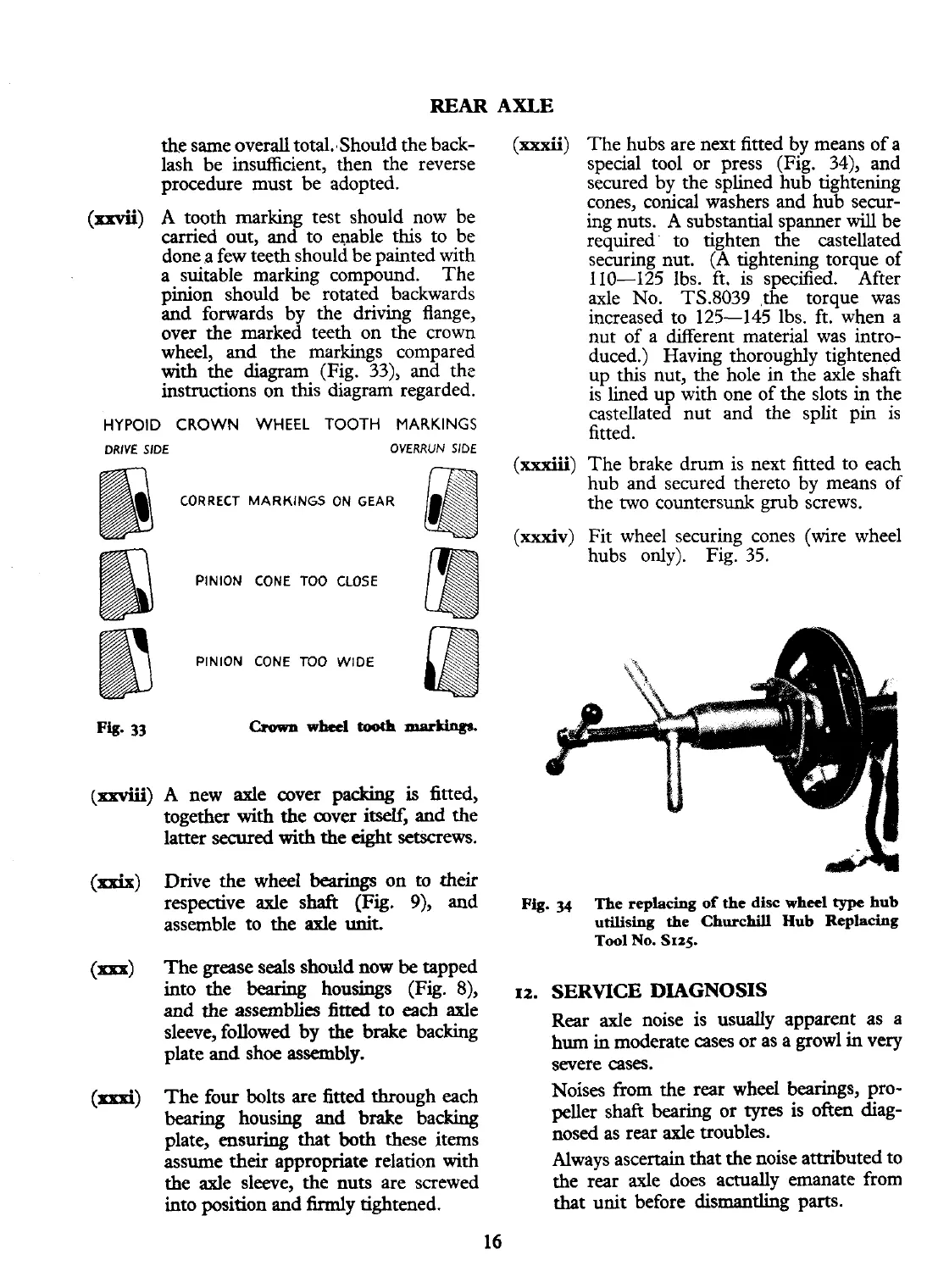
(xxxii)
The hubs are next fitted by means of
a
special tool or press (Fig. 34), and
secured by the splined hub tightening
cones, conical washers and hub secur-
ing nuts. A substantial spanner
will
be
required to tighten the castellated
securing nut. (A tightening torque of
110-125 lbs. ft. is specified. After
axle No. TS.8039 ,the torque was
increased to 125-145 lbs. ft. when a
nut of a different material was intro-
duced.) Having thoroughly tightened
up this nut, the hole in the axle shaft
is lined up with one of the slots in the
castellated nut and the split pin is
fitted.
(xxxiii)
The brake drum is next fitted to each
hub and secured thereto by means of
the two countersunk grub screws.
(xxxiv)
Fit wheel securing cones (wire wheel
hubs only). Fig. 35.
Fig.
34
The replacing
of
the
disc
wheel
type
hub
utilising
the
Churchill
Hub
Replacing
Tool
No.
SIZS.
12.
SERVICE
DIAGNOSIS
Rear
axle noise is usually apparent as a
hum in moderate
cases
or as a growl in very
severe cases.
Noises from the rear wheel bearings, pro-
peller shaft bearing or tyres is often diag-
nosed as rear axle troubles.
Always ascertain that the noise attributed to
the rear axle does actually emanate from
that unit before dismantling parts.
 Loading...


