FRONT SUSPENSION AND STEERING
7.
TO SET STEERING LOCK STOPS
Select a space of level ground and run
the car gently forward so that the front
wheels run on to the Churchill Turning
measure and the back wheels on to
blocks as high as the Churchill gauge
(Fig.
4).
This will ensure that the car maintains
its level.
Measure the wheel movement from the
straight ahead position.
Adjust the eccentric roller by first
loosening the setscrew and then turn
the roller itself.
When the correct degree of adjustment
is attained, tighten down the setscrew
so that the roller will remain in contact
with the vertical
link.
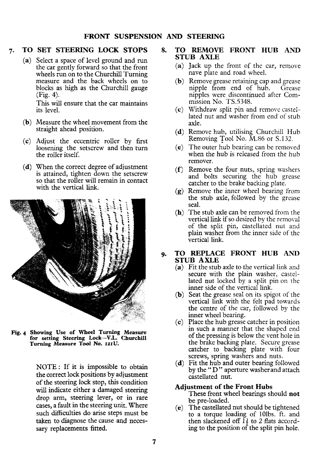
Fig.
4
Showing Use of
Wheel
Turning
Measure
for setting Steering
Lock-V.L. Churchill
Turning
Measure
Tool
No.
IZIU.
NOTE
:
If
it
is impossible to obtain
the correct lock positions by adjustment
of the steering lock stop, this condition
will
indicate either a damaged steering
drop arm, steering lever, or
in
rare
cases, a fault
in
the steering unit. Where
such difficulties do arise steps must be
taken to diagnose the cause and neces-
sary replacements fitted.
8.
TO REMOVE FRONT HUB
AND
STUB AXLE
Jack up the front of the car, remove
nave plate and road wheel.
Remove grease retaining cap and grease
nipple from end of hub. Grease
nipples were discontinued after Com-
mission No.
TS.5348.
Withdraw split pin and removc castel-
lated nut and washer from end of stub
axle.
Remove hub, utilising Churchill Hub
Removing Tool No. M.86 or S. 132.
The outer hub bearing can be removed
when the hub is released from the hub
remover.
Remove the four nuts, spring washers
and bolts securing the hub grease
catcher to the brake backing plate.
Remove the inner wheel bearing from
the stub axle, followed by the grease
seal.
The stub axle can be removed from the
vertical link if so desired by the removal
of the split pin, castellated nut and
plain washer from the inner side of
the
vertical link.
9.
TO REPLACE FRONT HUB
AND
STUB AXLE
(a)
Fit the stub axle to the vertical link and
secure with the plain washer, castel-
lated nut locked by a split pin on the
inner side of the vertical link.
(b) Seat the grease seal on its spigot of the
vertical
link
with the felt pad towards
the centre of the car, followed by the
inner wheel bearing.
(c) Place the hub grease catcher in position
in such a manner that the shaped end
of the pressing is below the vent hole in
the brake backing plate. Secure grease
catcher to backing plate with four
screws, spring washers and nuts.
(d)
Fit the hub and outer bearing followed
by the
"D"
aperture washerand attach
castellated nut.
Adjustment of the Front
Hubs
These front wheel bearings should
not
be pre-loaded.
(e)
The castellated nut should be tightened
to a torque loading of 10lbs. ft. and
then slackened off
14
to
2
flats accord-
ing to the position of the split pin hole.
 Loading...


