FRONT SUSPENSION AND STEERING
The hub bearings are' now considered
to be correctly adjusted and the castel-
lated nut can be locked with the split
pin.
(f)
Fit the grease retaining cap and grease
nipple to hub, and grease hub.
(g)
Replace road wheel and nave plate.
Remove lifting jack from under front
of
car.
10.
TO REMOVE FRONT SHOCK
ABSORBER
(a)
Jackup the car, place supporting stands
under the chassis frame and remove
lifting jack. Remove road wheel.
(b) Partially compress the front road spring
by placing a small lifting jack under the
spring pan.
(c)
Remove the lock nut and nut from
upper end of shock absorber, fol-
lowed by a plain washer and upper
rubber mounting.
(d) Detach the rebound rubber and its
bracket from the side of the chassis
frame after removing the nuts, lock
washers and two long bolts.
(e) Remove the lifting jack from below the
spring pan.
(f)
Remove the four nuts and lock washers
from the underneath and centre of the
spring pan. After withdrawing the re-
bound rubber abutment plate the
shock absorber can be withdrawn
through the spring plate.
(g)
After removing the shock absorber
from the car, its lower attachment
brackets can be removed. Lift the
tabs of the locking
plate and remove
the setscrew followed by one bracket
and a rubber bush.
(h)
The second bracket is removed from
the shock absorber together with the
rubber bush, the latter can be with-
drawn from the fulcrum pin of the
bracket assembly.
11.
TO FIT SHOCK ABSORBER
(a)
Examine all rubber bushes to ascertain
that they are in good order. Also ensure
that the fulcrum pin is secui-ely welded
to the shock absorber attachment
bracket.
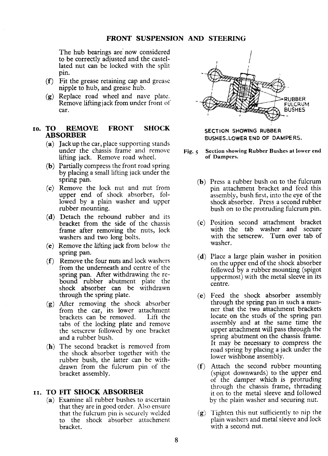
SECTION
SHOWING
RUBBER
EUSHES.LOWER
END
OF
DAMPERS.
Fig.
5
Section showing Rubber Bushes
at
lower end
of Dampers.
(b) Press a rubber bush on to the fulcrum
pin attachment bracket and feed this
assembly, bush first, into the eye of the
shock absorber.
Press a second rubber
bush on to the protruding fulcrum pin.
(c)
Position second attachment bracket
with the tab washer and secure
with the setscrew. Turn over tab of
washer.
(d)
Place a large plain washer in position
on the upper end of the shock absorber
followed by a rubber mounting (spigot
uppermost) with the metal sleeve in its
centre.
(e) Feed the shock absorber assembly
through the spring pan in such a man-
ner that the two attachment brackets
locate on the studs of the spring pan
assembly and at the same time the
upper attachment will pass through the
spring abutment on the chassis frame.
It may be necessary to compress the
road spring by placing a jack under the
lower wishbone assembly.
(f)
Attach the second rubber mounting
(spigot downwards) to the upper end
of the damper which
is
protruding
through the chassis frame, threading
it on to the metal sleeve and followed
by the piain washer and securing nut.
(g)
Tighten this nut suficiently ro nip the
plain washers and metal sleeve and lock
with a second nut.
 Loading...


