FRONT SUSPENSION AND STEERING
(h)
Place the rebound rubber abutment
\,
plate in position on the lower attach-
ment studs (welded to the spring pan)
with the apex of the wedge pointing
towards the centre of the car. Secure
with nuts and lock washers.
(i)
Utilising two long bolts, nuts and lock
washers secure the rebound rubber and
its bracket to the chassis frame.
(j)
Remove the lifting jack from under the
lower wishbones and replace the road
wheel.
(k)
Jack up front of car to remove support
stands, finally remove jack.
12.
TO REMOVE FRONT ROAD
SPRING
(a)
Remove front shock absorber as de-
scribed on page
8.
(b)
Withdraw the split pins from the
castellated nuts on the underside of the
lower wishbones. Remove the centre
nut and bolt from the front wishbone
arm and the bump rubber assembly
from the rear wishbone arm. Feed
two guide pins into the vacant holes.
(c)
Place a small lifting jack under the
spring pan, with a suitable packing
between jack and pan to prevent darn-
age to the shock absorber attachment
studs on the latter.
(d)
Remove the four remaining nuts secur-
ing the spring pan to the wishbone
arms and lower jack, easing the guide
pins through the wishbone
arms.
(e)
The spring can be withdrawn from its
upper abutment together with rubber
washers and distance piece.
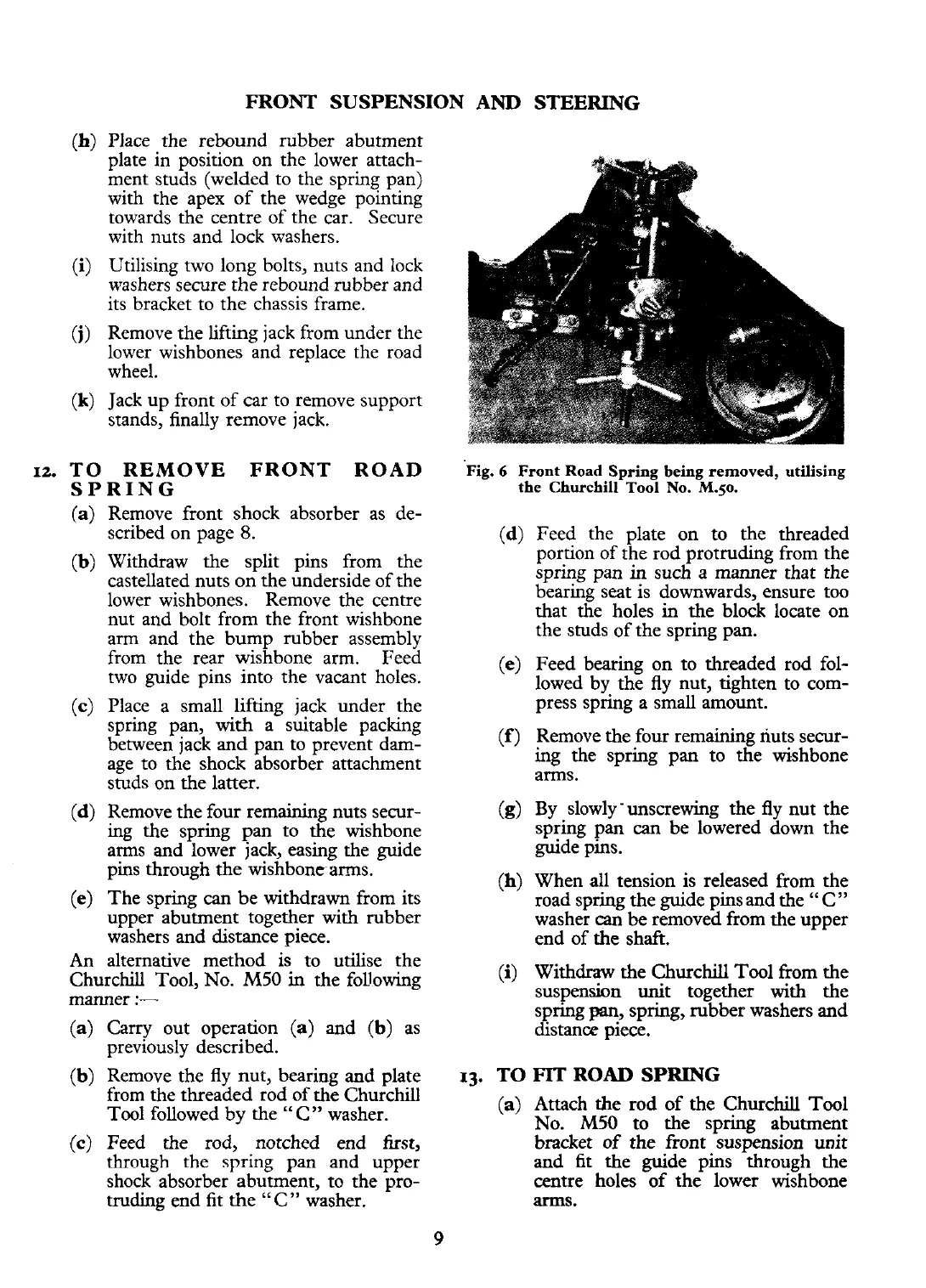
Fig.
6
Front Road Spring being removed, utilising
the Churchill Tool No.
M.50.
(d)
Feed the plate on to the threaded
portion of the rod protruding from the
spring pan
in
such a manner that the
bearing seat is downwards, ensure too
that the holes in the block locate on
the studs of the spring pan.
(e)
Feed bearing on to threaded rod fol-
lowed by the fly nut, tighten to com-
press spring a small amount.
(f)
Remove the four remaining nuts secur-
ing the spring pan to the wishbone
arms.
(g)
By slowly 'unscrewing the fly nut the
spring pan
can
be lowered down the
guide pins.
(h)
When all tension is released from the
road spring the guide pins and the
"
C
"
washer
can
be
removed from the upper
end of
the
shaft.
An alternative method is to utilise the
Churchill Tool, No.
M50
in
the following
(i)
Withdraw the Churchill Tool from the
manner
:-
suspension unit together with the
spring
pn,
spring, rubber washers and
(a)
Carry out operation
(a)
and
(b)
as
distance piece.
previously described.
(b)
Remove the fly nut, bearing and plate
13.
TO
FIT
ROAD SPRING
from the threaded rod of the Churchill
Tool followed by the "C" washer.
(a)
Attach
the
rod of the Churchill Tool
No.
M50
to the s~rinp: abutment
(c)
Feed the rod, notched end first, bracket of the front 'sus~ension unit
through the spring pan and upper and fit the guide pins through the
shock absorber abutment, to the pro- centre holes of the lower wishbone
truding end fit the "C" washer. arms.
 Loading...


