FRONT SUSPENSION
AND
STEERING
Assemble the alloy distance piece
(spigot downward) on the road spring
with a rubber washer interposed be-
tween, and position a second rubber
washer on the spring's lower extremity.
The spring and distance piece assembly
is offered up to the front suspension
unit followed by the spring pan, the
latter located on the guide pins.
Fit the plate to the threaded rod of the
Churchill Tool in such
a
manner that
the bearing
will
seat in its recess and
the studs of the spring pan in their
recesses. Follow with the bearing and
fly nut.
The fly nut of the tool is turned to
compress the spring. Ensure that,
when the spring pan closes to the wish-
bone arms that it is located on the
attachment studs at the inner ends
of the wishbone. Secure and lock
washers and castellated nuts and fit two
bolts with castellated nuts and lock
washers at the trunnion end of the
wishbone arm.
When the spring pan is secured to the
wishbone arms the Churchill Tool can
be removed and the guide pins with-
drawn from the wishbone arm.
The spring pan is finally secured to the
wishbone arms by a nut, bolt and lock
washer at the front arm and a bump
rubber assembly at the rear arm.
Lock all six nuts with split pins.
The shock absorber can now be fitted
as described on page
8.
TO
REMOVE
AND
DISMANTLE
FRONT SUSPENSION UNIT
Before dismantling the units, suitably mark
the components so that they can be returned
to their relative positions.
two
of the four bolts securing the
brake backing plate to the vertical
link,
followed by the upper two bolts.
These bolts pass through the vertical
link
and distance pieces and thence
through the steering lever, on the
withdrawal of these bolts it will be
necessary to hold the steering lever
and collect the bushes. Alternately the
brake plate can be removed from the
vertical
link
without draining the
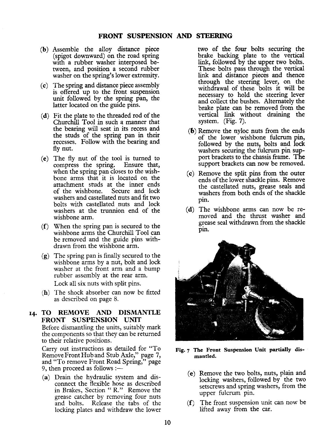
system. (Fig.
7).
(b)
Remove the nyloc nuts from the ends
of the lower wishbone fulcrum pin,
followed by the nuts, bolts and lock
washers securing the
fulcrum
pin sup-
port brackets to the chassis frame. The
support brackets
can
now be removed.
(c) Remove the split pins from the outer
ends of the lower shackle pins. Remove
the castellated nuts, grease seals and
washers from both ends of the shackle
pin.
(d) The wishbone arms can now be re-
moved and the thrust washer and
grease seal withdrawn from the shackle
pin.
Carry
out instructions as detailed for "To
Q.,
-l-he ~~~~t ~~~~~~~i~~ unit partially dis-
Remove Front Hub and Stub Axle," page
7,
mantled.
and "To remove Front Road Spring," page
A
v-
9,
then proceed as follows
:-
(e)
Remove the two bolts, nuts, plain and
(a)
Drain the hydraulic system and dis-
locking washers, followed by the two
connect the flexible hose as described
setscrews and spring washers, from the
in Brakes, Section
"
R."
Remove the
upper fulcrum pin.
grease catcher by removing four nuts
and bolts. Release the tabs of the
(f)
The front suspension unit
can
now be
locking plates and withdraw the lower
lifted away from the car.
 Loading...


