FRONT SUSPENSION
AND
STEERING
Withdraw the split pin from the castel-
lated nut securing the ball joint as-
sembly to the upper wishbone arm.
Remove the castellated nut and with-
draw the ball joint assembly from the
wishbone arms, collecting the distance
piece as the ball joint is moved.
Withdraw the split pin and remove the
nut and plain washer securing the ball
joint assembly to the vertical
link
and
withdraw ball joint.
Withdraw the split pins from the
castellated nuts at the outer ends of the
upper inner
fulcrum pin. Remove the
large diameter plain washers and the
outer rubber bushes.
The wishbone arms
can
now be re-
moved and the second rubber bush
withdrawn from the fulcrum pin.
Remove the steering stop screw from
the lower end of the vertical
link
and
detach the bottom trunnion assembly
from the vertical
link
and collect the oil
seal situated between the vertical
link
and the trunnion assembly.
TO
ASSElMBLE
AND
REPLACE
FRONT SUSPENSION
UNIT
Assembly is made with strict regard to the
markings on certain parts to ensure that
they are returned to the same relative
position.
(i)
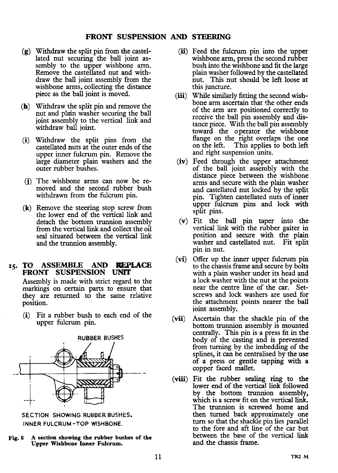
Fit a rubber bush to each end of the
upper fulcrum pin.
RUBBER BUSHES
(ii)
Feed the fulcrum pin into the upper
wishbone arm, press the second rubber
bush into the wishbone and fit the large
plain washer followed by the castellated
nut. This nut should be left loose at
this juncture.
(iii)
While similarly fitting the second wish-
bone arm ascertain that the other ends
of the arm are positioned correctly to
receive the ball pin assembly and dis-
tance piece. With the ball pin assembly
toward the operator the wishbone
flange on the right overlaps the one
on the left. This applies to both left
and right suspension units.
(iv)
Feed through the upper attachment
of the ball joint assembly with the
distance piece between the wishbone
arms and secure with the plain washer
and castellated nut locked by the split
pin. Tighten castellated nuts of inner
upper fulcrum pins and lock with
split pins.
(v)
Fit the ball pin taper into the
vertical
link
with the rubber gaiter in
position and secure with the plain
washer and castellated nut. Fit split
pin in nut.
(vi)
Offer up the inner upper fulcrum pin
to the chassis frame and secure by bolts
with a plain washer under its head and
a lock washer with the nut at the points
near the centre line of the car. Set-
screws and lock washers are used for
the attachment points nearer the ball
ioint assembly.
(vii)
Ascertain that the shackle pin of the
bottom trunnion assembly is mounted
centrally. This pin is a
ress
fit
in
the
body of the casting an
B
is prevented
from turning by th; imbeddhg of the
splines, it
can
be centralised by the use
of a press or gentle tapping
with
a
copper faced mallet.
(viii)
Fit the rubber sealing ring to the
lower end of the vertical
link
followed
by the bottom trunnion assembl
which is a screw fit on the vertical
d
The trunnion is screwed home and
SECTION SHOWING RUBBER BUSHES.
then turned back approximately one
INNER FULCRUM-TOP WISHBONE.
turn
SO
that the shackle pin lies parallel
to the fore and
aft
line of the car but
Fig.
8
A
section showing
the
rubber bushes of the
between the base of the vertical
link
Upper Wishbone Inner
Fulcrum.
and the chassis frame.
 Loading...


