FRONT SUSPENSION
AND
STEERING
Feed the locking washer and steering
lock stop bush on to the steering stop
securing bolt and attach to the bottom
trunnion assembly. The bolt is left
finger tight at this juncture.
Fit two rubber bushes to the inner
lower
fulcrum
pin situated on the
upper face of the chassis frame, one
to each side.
Fit two thrust washers to the shackle
pin, one to each side, followed by the
grease seal.
The lower wishbone arms are now
fitted over the rubber bushes on the
inner fulcrum pin and on to the shackle
pin simultaneously. Fit a second pair
of rubber bushes on to the inner
fulcrum pin (and into the lower wish-
bone arm) followed by the support
bracket, the two holes of which are
lowermost. Secure with the nyloc nut
but do not fully tighten at this juncture.
RUBBER
BUSHES
SECTION SHOWING
RUBBER
BUSHES
LOWER WISHBONE-INNER
FULCRUM.
Fig.
9
Section showing Rubber Bushes at Lower
Wishbone--Inner Fulcrum.
(xiii)
Secure the support brackets to the
brackets welded to the chassis frame
utilising bolts, nuts with lock washer.
Tighten the nyloc nuts of the inner
lower fulcrum pins until they are solid.
(xiv)
Fit to both ends of the shackle pin at
the outer end of each wishbone arm, a
thrust washer followed by a special lock
washer (collar inwards) followed by
the rubber grease seals. These lock
washers are prevented from rotating by
self cutting splines. Feed on the castel-
lated nuts to the ends of the shackle pin
and obtain the necessary end float
before
locking with the split pin,
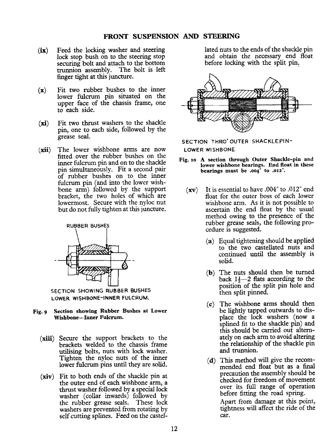
SECTION
THRO'OUTER
SHACKLEPIN-
LOWER WISHBONE.
Fig.
10
A
section through Outer Shackle-pin and
lower wishbone bearings. End float in these
bearings must be
.004" to .OIZ".
(m)
It
is essential to have
.004"
to
.012"
end
float for the outer boss of each lower
wishbone arm. As it is not possible to
ascertain the end float by the usual
method owing to the presence of the
rubber grease seals, the following pro-
cedure is suggested.
(a)
Equal tightening should be applied
to the two castellated nuts and
continued until the assembly is
solid.
(b)
The nuts should then be turned
back 1+2 flats according to the
positioG of the split pin
gale
and
then split pinned.
(c)
The wishbone arms should then
be lightly tapped outwards to dis-
place the lock washers (now a
splined
fit
to the shackle pin) and
this should be carried out altern-
ately on each arm to avoid altering
the relationship of the shackle pin
and trunnion.
(d)
This method
will
give the recom-
mended end float but as a final
precaution the assembly should be
checked for freedom of movement
over its
full
range of operation
before fitting the road spring.
Apart from damage at this point,
tightness
will
affect the ride of the
car.
 Loading...


