FRONT SUSPENSION
AND
STEERING
The drop arm must only be removed by a
special puller, Tool No. M.91 is re-
commended, a hammer must not be used
since any blow would be transferred to the
hardened conical pin in the rocker shaft
lever which would
in
turn
indent the cam
gear and damage the unit.
The drop arm should only be replaced when
the trunnion bracket is in position on the
rocker shaft housing. The arm is set in such
a manner that it will
ooint rearwards and
downwards and the scribe line on the end of
the rocker shaft will align with that on the
drop arm and appear to be continuous.
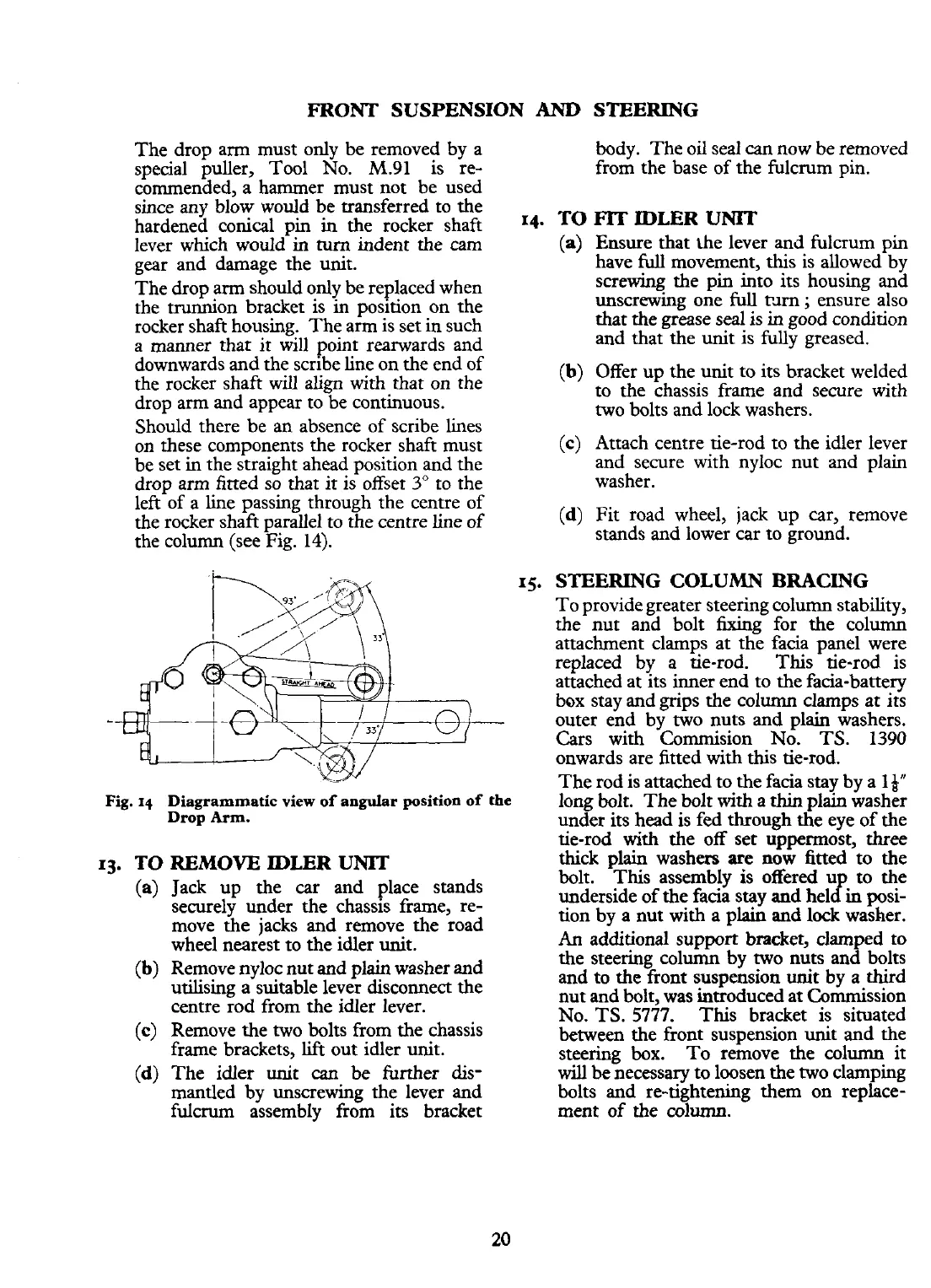
Should there be an absence of scribe lines
on these components the rocker shaft must
be set in the straight ahead position and the
drop arm fitted so that it is offset
3"
to the
left of a line passing through the centre of
the rocker
shaft parallel to the centre line of
the column (see Fig. 14).
body. The oil seal
can
now be removed
from the base of the fulcrum pin.
14.
TO
FIT
IDLER
UNIT
(a) Ensure that he lever and fulcrum pin
have
full
movement, this is allowed by
screwing the pin into its housing and
unscrewing one
full
mm
;
ensure also
that the grease seal is in good condition
and that the unit is fully greased.
(b)
Offer up the unit to its bracket welded
to the chassis frame and secure with
two bolts and lock washers.
(c)
Attach centre tie-rod to the idler lever
and secure with nyloc nut and plain
washer.
(d)
Fit road wheel, jack up car, remove
stands and lower car to ground.
15.
STEERING COLUMN BRACING
To provide greater steering column stability,
the nut and bolt fixing for the column
attachment clamps at the facia panel were
replaced by a tie-rod. This tie-rod is
attached at its inner end to the facia-battery
box stay and grips the column clamps at its
outer end by two nuts and plain washers.
Cars with
Commision No. TS. 1390
onwards are fitted with this tie-rod.
The rod is attached to the facia stay by a
14"
Fig.
14
Diagrammatic
view
of
angular
position
of
the
long bolt. The bolt with a
thin
plain washer
Drop
Arm.
under its head is fed through the eye of the
tie-rod
with
the off set u~~ermost,
three
TO
REMOVE IDLER
UNIT
(a) Jack up the car and place stands
securely under the chassis frame, re-
move the jacks and remove the road
wheel nearest to the idler unit.
(b)
Remove nyloc nut and plain washer and
utilising a suitable lever disconnect the
centre rod from the idler lever.
(c)
Remove the two bolts from the chassis
frame brackets,
lift
out idler unit.
(d)
The idler unit
can
be further dis-
mantled by unscrewing the lever and
fulcrum assembly from its bracket
thick
plain
washers are
n&
fitted-to the
bolt. This assembly
is
offered u to the
underside of the facia stay and helfin posi-
tion by a nut with a plain and
lock
washer.
An
additional support bracket, clamped to
the steering column by two nuts and bolts
and to the front suspension unit
by
a third
nut and bolt,
was
introduced at Commission
No.
TS.
5777.
This bracket is situated
between the front suspension unit and the
steering box. To remove the column it
will
be necessary to loosen the two clamping
bolts and re-tightening them on replace-
ment of
the
column.
 Loading...


