FRONT SUSPENSION AND STEERING
TELESCOPIC (ADJU
STEERING UNIT
'STABLE)
Description
(Fig.
IS)
This unit is very similar to the normal
equipment apart from three main
features
:-
Steering Unit
(i) The inner column is of similar
length, but its steering wheel
attachment splines are of a much
greater length.
(ii)
The outer column is shorter
than
the normal equipment to allow the
increased length of the inner
column splines to be utilised.
(iii)
The distance of the steering wheel
from the driver
can
by
2)"
inches.
Steering
Wheel
The steering wheel is the three equi-
distance spoke type and is a slide
fit
on
the splines of the inner column, it
is
held at its
maximum
point of extension
by a circlip fitted in an annular recess
machined at the top of the splines.
(See Fig.
16.)
The lower length of splines, between
the underside of the steering wheel and
the top of the outer column is covered
by a telescopic metal shroud.
This metal shroud is supported at its
smaller (bottom) end by a spigotted
bakelite washer and positioned at its
upper end under the steering wheel
locking sleeve
by
a plated steel cup
washer.
The steering wheel hub consists of a
steel internally splined sleeve as its
centre,
with
a cast
aluminium
surround.
The lower end extruding portion of the
steel insert is split, threaded and is
rovided with
an
externally tapered
L
ge to accommodate
aluminium
steel
lined
locking sleeve.
An
internal
taper,
corresponding to
that on the lower extension of the
steering wheel hub,
is
machined at the
bottom of the locking sleeve bore.
When
the locking sleeve is screwed to
the hub
insert,
a
chuck action is
developed, thus locking the steering
wheel to the external splines on the
inner
column.
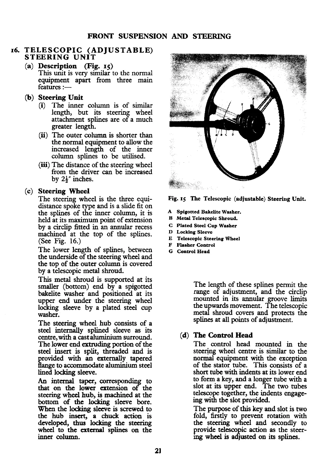
Fig.
15
The Telescopic (adjustable) Steering Unit.
A
Spigoned Bakelite Washer.
B Metpl Teleswpic Shroud.
C Plated Steel Cup Waaher
D
Locking Sleeve
E
Telescopic Steering Wheel
F
Plasher Control
G
Control Head
The length of these splines permit the
range of adjustment, and the circlip
mounted in its
annular
groove limits
the upwards movement. The telescopic
metal shroud covers and protects the
splines at
all
points of adjustment.
(d)
The
Control
Head
The control head mounted in the
stee~g wheel centre is similar to the
normal equipment
with
the exception
of the stator tube. This consists of a
short tube
with
indents at
its
lower end
to form a key, and a longer tube
with
a
slot at its upper end. The two
tubes
telescope together, the indents engage-
ing
with
tbe slot provided.
The purpose of this key and slot is two
fold, firstly to prevent rotation with
the steering wheel and secondly to
provide telesco ic action as the steer-
mg
wheel
is
a
d?
lusted on its splines.
 Loading...


