FRONT SUSPENSN
3N
AND
STEERING
17.
TO FIT THE TELESCOPIC
(ADJUSTABLE) STEERING
UNIT
AND
STEERING WHEEL
(a)
With the exception of the steering
wheel the fitting of this unit does not
diier from that of the normal equip-
ment. Follow the sequence given in
"To Fit Steering Unit" (see page 18,
operations
(a)
to
(h)).
(b) Ensuring that the
car
is on level ground
and the road wheels are aligned in the
straight ahead position, thread the
bakelite washer, spigot uppermost, over
the splines of the inner column and
locate it on the top of the outer column.
Slightly grease the splines.
(c)
Fit the telescopic metal shroud on to
the steering column placing the smaller
diameter downwards to engage the
spigot of the bakelite washer. The
large diameter end of the metal shroud
fits into the metal cupped washer, the
plane side of which abuts against the
locking sleeve.
(d)
With the thee spokes of the steering
wheel forming a
"Y"
and ensuring that
the locking sleeve is loosened, position
the wheel on the splines of the inner
column so that the lowermost spoke is
pointing
vertically downwards.
(e)
Push the wheel down to its fullest ex-
tent and tighten locking sleeve. This
will
uncover an annular groove in the
upper end of the inner column. The
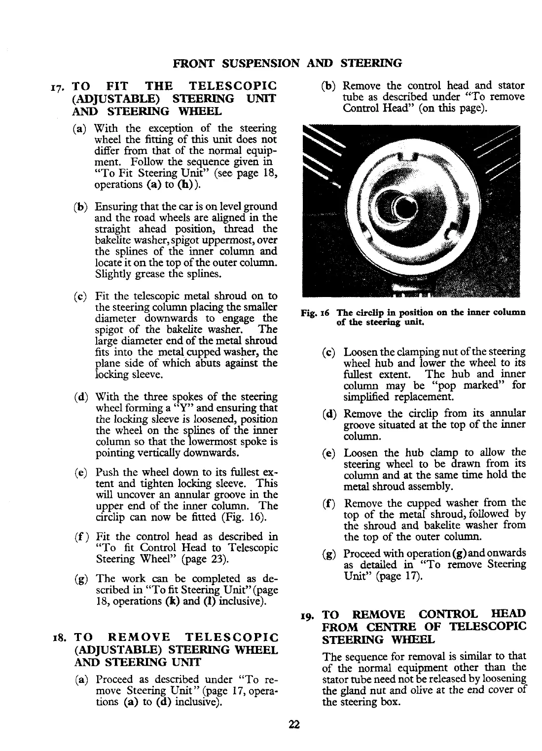
circlip
can
now be fitted (Fig. 16).
(f)
Fit the control head as described in
"To fit Control Head to Telescopic
Steering Wheel" (page
23).
(g)
The work
cm
be completed as de-
scribed in "To fit Steering UnitY'(page
18, operations
(k)
and
(1)
inclusive).
18.
TO REMOVE TELESCOPIC
(ADJUSTABLE) STEERING WHEEL
AND
STEERING
UNIT
(a) Proceed
as described under "To re-
move Steering Unit
"
(page 17, opera-
tions (a) to (d) inclusive).
(b) Remove the control head and stator
tube as described under "To remove
Control Head" (on this page).
Fig.
16
The
circlip
in
position on
the inner
column
of
the
steering
unit.
(c) Loosen the clamping nut of the steering
wheel hub and lower the wheel to its
fullest extent. The hub and inner
column may be "pop marked" for
simplified replacement.
(d) Remove the circlip from its annular
groove situated at the top of the inner
column.
(e)
Loosen the hub clamp to allow the
steering wheel to be drawn from its
column and at the same time hold the
metal shroud assembly.
(f)
Remove the cupped washer from the
top of the metal shroud, followed by
the shroud and bakelite washer from
the top of the outer column.
(g)
Proceed
with
operation(g) and onwards
as detailed in "To remove Steering
Unit" (page 17).
19. TO REMOVE CONTROL
HEAD
FROM
CENTRE
OF TELESCOPIC
STEERING
WHEEL
The sequence for removal is similar to that
of the normal equipment other than the
stator tube need not be released by loosening
the gland nut and olive at the end cover of
the steering
box.
 Loading...


