ROAD SPRINGS
AND
SHOCK ABSORBERS
volume equal to the displacement of the
piston rod (D) passes through the ports
(E)
in the piston rod guide (F), down the anti-
foam
tube
(G) and into the reservoir (H) by
way of the rebound valve (RV).
On the rebound stroke, however, the piston
valve
(Pv)
closes and
oil
passes through the
ports
(E)
in the piston rod guide (F), down
the anti-foam tube
(G),
opens the rebound
valve (RV) against the spnng load and passes
into the reservoir (H). At the same time the
foot valve plate (Fv) lifts and oil is recuper-
ated to the lower part
of
the cylinder (B).
General slow speed damping is accomplished
by bleed orifices
bult into the valve
mechanism.
The maximum load of compression (bump
is 200 lbs. and on extension (rebound
500 lbs.
4.
TO REMOVE OR
REPLACE
FRONT
SHOCK ABSORBER
This is detailed in the "Front Suspension,
Section G" under this heading.
REAR
SHOCK ABSORBER
I.
DESCRIPTION
(Fig.
5)
The shock absorber body is attached to the
brackets welded to the upper sides of the
chassis
flame and linked to the rear axle by
an
arm,
splined to the shock absorber
spindle, and a connecting
link
to a plate
assembly mounted on the underside of the
road spring.
The body
has
two equal sized cylinders
accommodating steel pistons which are recip-
ricated through short connecting rods and
are coupled to the
crank
plate which is
attached to the spindle.
When the axle moves relative to the
car
(this
movement is allowed b
the road
spring) the
arm
is moved up or
1
own, and as
it is splined to a spindle, the latter rotates.
The spindle is a splined fit in the
crank
plate, this plate being coupled by
means
of
connecting rods to the pistons, in which
are situated
lightly
loaded recuperating
valves. The pressure is built up in one
cylinder or the other and since the cylinders
are connected by
ports
in the body to the
valve chamber, this pressure is dependent
on the valve setting.
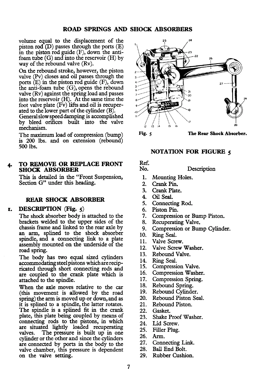
Fig.
S
The
Rear
Shock
Absorber.
Ref.
No.
NOTATION FOR
FIGURE
5
Description
Mounting Holes.
Crank
Pin.
Crank
Plate.
Oil
Seal.
Connecting Rod.
Piston Pin.
Compression or Bump Piston.
Recuperating Valve.
Compression or Bump Cylinder.
Ring Seal.
Valve Screw.
Valve Screw Washer.
Rebound Valve.
Ring Seal.
Compression Valve.
Compression Washer.
Compression Spring.
Rebound Spring.
Rebound Cylinder.
Rebound Piston Seal.
Rebound Piston.
Gasket.
Shake Proof Washer.
Lid Screw.
Filler Plug.
Ann.
Connecting
Link.
Ball End Bolt.
Rubber Cushion.