ROAD SPRINGS
AND
SHOCK ABSORBERS
The unit is filled to the base of the Mer plug
boss which prevents over filling and main-
tains the necessary air space essential to
satisfactory operation. The working mech-
anism is completely submerged in oil which
is prevented from leaking along the spindle
by means of oil seals.
The damper requires very little attention
but the fluid level should be checked every
15,000
miles.
It
should be topped up to the
lower reaches of the filler boss and only with
Armstrong Shock Absorber Oil No.
624
should be used, the guarantee of this partic-
ular component becomes void if any other
oil is used.
Every precaution must be taken to ensure
that no lubrication is given to the rubber
mountings of the connecting
link.
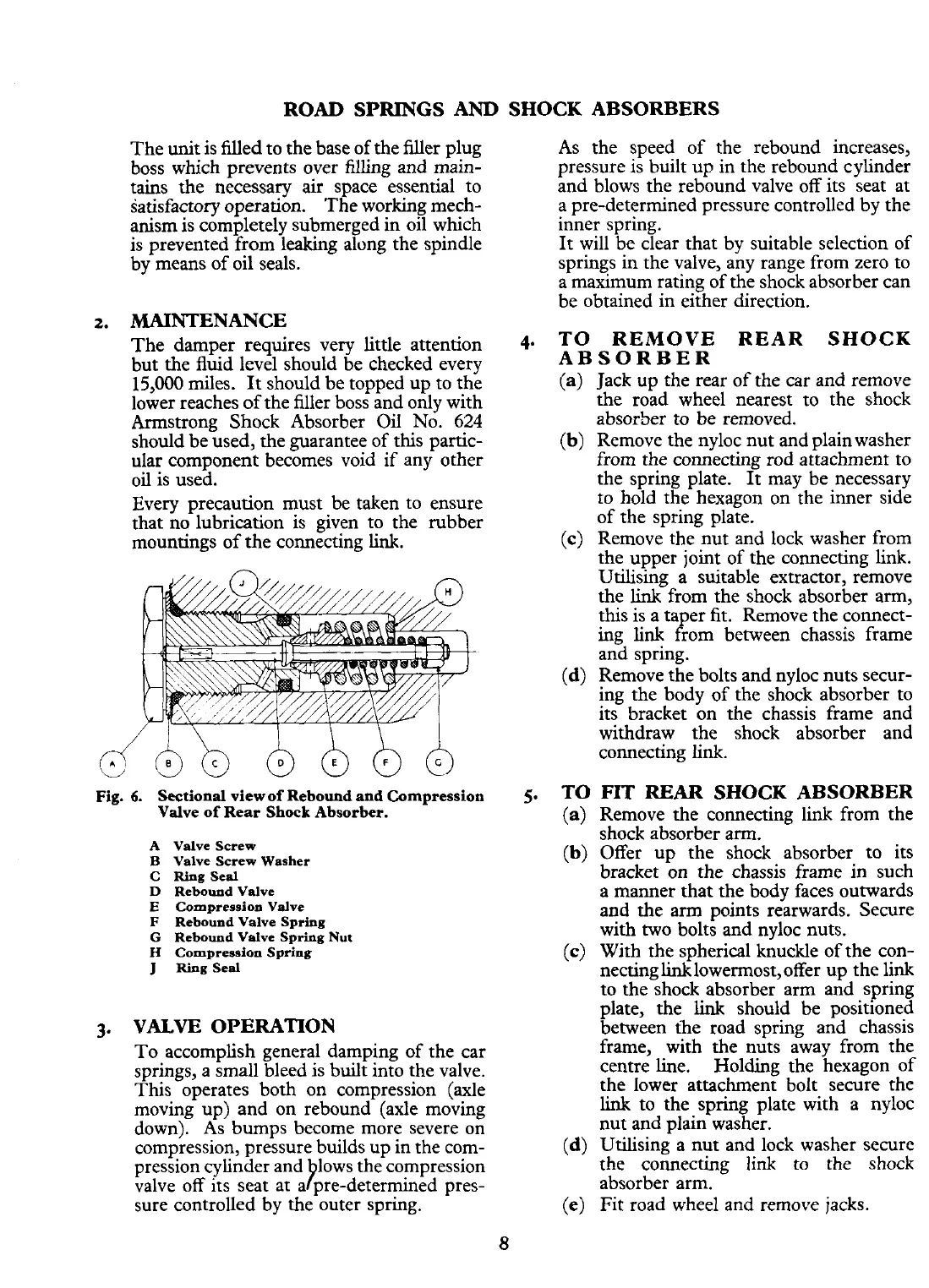
Fig.
6.
Sectional viewof Rebound and Compression
Valve of Rear Shock Absorber.
A
Valve Screw
B
Valve Screw Washer
C Ring Seal
D
Rebound Valve
E
Compression Valve
F
Rebound Valve Spring
G
Rebound Valve Spring
Nut
H
Compression Spring
J
Ring Seal
3.
VALVE OPERATION
To accomplish general damping of the car
springs, a small bleed is built into the valve.
This operates both on compression (axle
moving up) and on rebound (axle moving
down). As bumps become more severe on
compression, pressure builds up in the com-
pression cylinder and lows the compression
P
valve off its seat at a pre-determined pres-
sure controlled by the outer spring.
As the speed of the rebound increases,
pressure is built up in the rebound cylinder
and blows the rebound valve off its seat at
a pre-determined pressure controlled by the
inner spring.
It will be clear that by suitable selection of
springs in the valve, any range from zero to
a maximum rating of the shock absorber can
be obtained in either direction.
4.
TO REMOVE REAR SHOCK
ABSORBER
(a) Jack up the rear of the car and remove
the road wheel nearest to the shock
absorber to be removed.
(b)
Remove the nyloc nut and plain washer
from the connecting rod attachment to
the spring plate.
It
may be necessary
to hold the hexagon on the inner side
of the spring plate.
(c) Remove the nut and lock washer from
the upper joint of the connecting link.
Utilising a suitable extractor, remove
the
link
from the shock absorber arm,
this is a taper
fit.
Remove the connect-
ing link from between chassis frame
and spring.
(d) Remove the bolts and nyloc nuts secur-
ing the body of the shock absorber to
its bracket on the chassis frame and
withdraw the shock absorber and
connecting link.
5.
TO
FIT
REAR
SHOCK ABSORBER
(a) Remove the connecting link from the
shock absorber arm.
(b)
Offer up the shock absorber to its
bracket on the chassis frame in such
a manner that the body faces outwards
and the arm points rearwards. Secure
with two bolts and nyloc nuts.
(c) With the spherical knuckle of the con-
necting linklowermost, offer up the link
to the shock absorber arm and spring
plate, the
link
should be positioned
between the road spring and chassis
frame, with the nuts away from the
centre line. Holding the hexagon of
the lower attachment bolt secure the
link
to the spring plate with a nyloc
nut and plain washer.
(d) Utilising a nut and lock washer secure
the connecting
link
to the shock
absorber arm.
(e)
Fit road wheel and remove jacks.
 Loading...


