PROPELLER
SHAFT
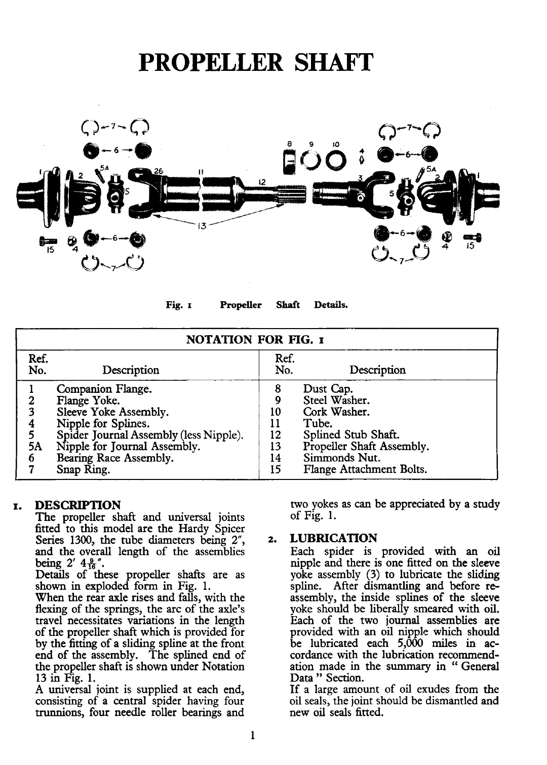
Fig.
I
Propeller
Shaft
Details.
Companion Flange.
Flange Yoke.
Sleeve Yoke Assembly.
Nipple for Splines.
Spider Journal Assembly (less Nipple).
Nipple for Journal Assembly.
Bearing Race Assembly.
Snav Ring.
NOTATION FOR
FIG.
I
Dust Cap.
Steel Washer.
Cork Washer.
Tube.
Splined Stub Shaft.
Propeller Shaft Assembly.
Simmonds Nut.
Flange Attachment Bolts.
Ref.
No. Description
I.
DESCRIPTION
The propeller shaft and universal joints
fitted to this model are the Hardy Spicer
Series 1300, the tube diameters being
2",
2-
and the overall length of the assemblies
Ref.
No. Description
-
being
2'
4fk".
Details of these ~ro~eller shafts are as
shown in exploded fgm in Fig.
1.
When the rear axle rises and falls, with the
flexing of the springs, the arc of the axle's
travel necessitates variations in the length
of the propeller shaft which is provided for
by the fitting of a sliding spline at the front
end of the assembly. The splined end of
the
vroveller shaft is shown under Notation
13
&
~i~.
l.
A universal joint is supplied at each end,
consistina of a central svider havine four
trunnion; four needle roller bearinis and
two yokes as
can
be appreciated by a study
of Fig. 1.
LUBRICATION
Each spider is provided with an oil
nipple and there is one fitted on the sleeve
yoke assembly (3) to lubricate the sliding
spline. After dismantling and before
re-
assembly, the inside splines of the sleeve
yoke should be liberally smeared with oil.
Each of the two journal assemblies are
provided with an oil nipple which should
be lubricated each 5,000 miles in ac-
cordance with the lubrication
recornmend-
ation made in the summary in
"
General
Data
"
Section.
If a large amount of oil exudes from the
oil seals, the joint should be dismantled and
new oil seals fitted.