PROPELLER
SHAFT
3.
MAINTENANCE INSTRUCTIONS
To
test
for
wear
Wear on the thrust faces is located by
testing the
lift
in the joint by hand.
Any circumferential movement of the shaft
relative to the flange yokes indicates wear
in the needle roller bearings and/or the
sliding splines.
+
REMOVAL
OF
PROPELLER
SHAFT
(a)
Jack
up one rear wheel clear of the
ground to enable the propeller shaft
to
be
rotated.
(b)
Remove nuts from bolts at both flange
yokes engaging ht gear, as necessary
to hold the shaft from turning when
slackening nuts.
(c)
Tap out bolts and remove propeller
shaft assembly.
5.
TO
DISMANTLE PROPELLER
sm
Before commencing to dismantle propeller
shaft see
if
"
arrow" location marks are
visible when the parts are clean. If no
marlungs are visible, re-mark to ensure
correct
re-assembly.
Having unscrewed the dust cap
(8,
Fig.
l),
pull sleeve yoke assembly
(3,
Fig.
1)
off
shaft.
Clean
enamel from snap rings and
top of bearings races. Remove
all
snap
rings by pinching ears together with
a
suitable pair of circlip pliers and sub-
sequently prising out these with
a
screw-
driver. If ring does not snap out of groove
readily, tap end of bearing race lightly in-
wards to relieve the ressure against ring.
Holding joint in le
f!
hand with splined
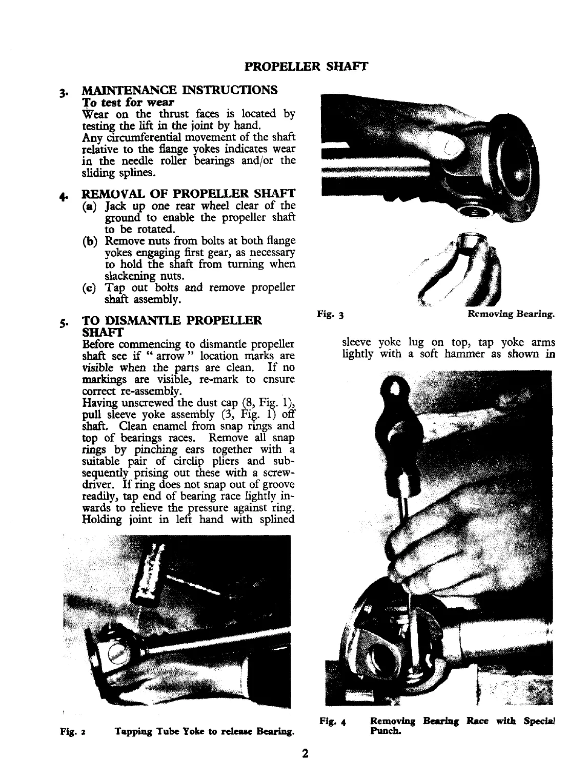
Fig.
3
Removing Bearing.
sleeve yoke lug on top, tap yoke arms
lightly with
a
soft hammer as shown
in
Fig.
2
Tapping
Tube
Yoke
to
relame
Bearing.
Fig.
4
Removing
Bcdq
Race
with
Specinl
Punch.