ELECTRICAL. EQUIPIMENT
(c) Belt Adjustment
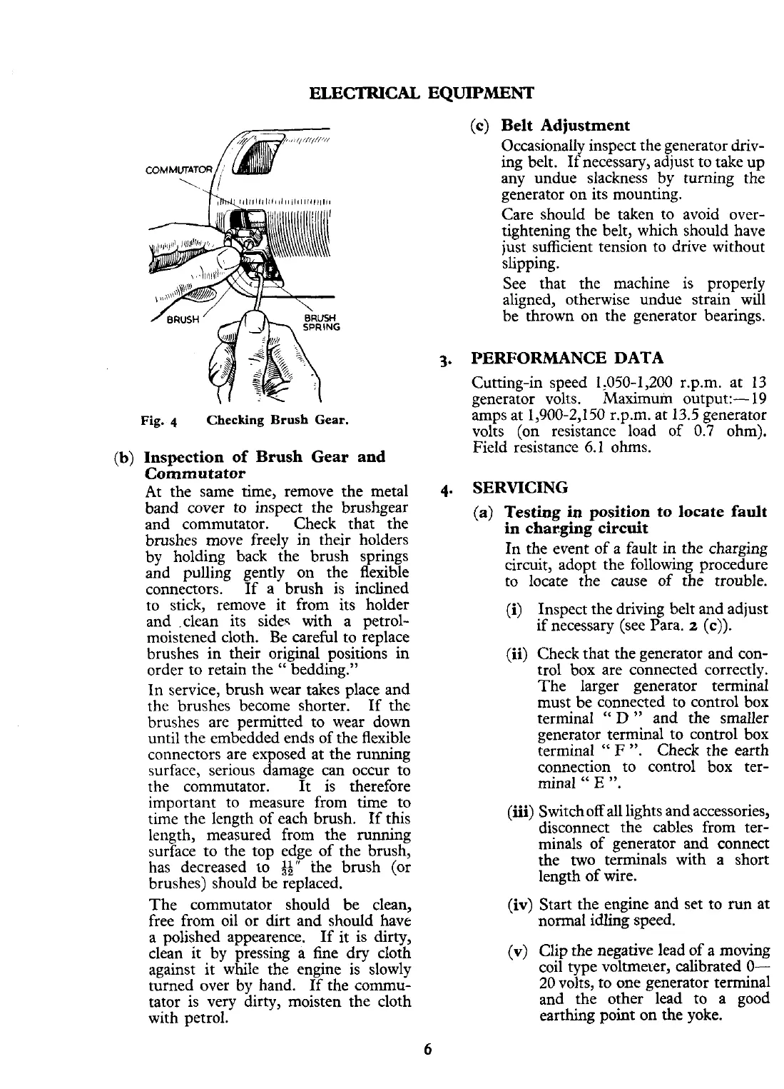
Fig.
q
Checking Brush Gear.
(b)
Inspection of Brush Gear and
Commutator
At the same time, remove the metal
4.
band cover to inspect the brushgear
and commutator. Check that the
brushes move freely in their holders
by holding back the brush springs
and pulling gently on the flexible
connectors. If a brush is inclined
to stick, remove it from its holder
and .clean its sides with a petrol-
moistened cloth. Be careful to replace
brushes in their original positions in
order to retain the
"
bedding."
In service, brush wear takes place and
the brushes become shorter. If the
brushes are permitted to wear down
until the embedded ends of the flexible
connectors are exposed at the running
surface, serious damage can occur to
the commutator.
It
is therefore
important to measure from time to
time the length of each brush. If this
length, measured from the running
surface to the top edge of the brush,
has decreased
10
g"
the brush (or
brushes) should be replaced.
The commutator should be clean,
free from oil or dirt and should have
a polished appearence. If it is
dirty,
clean it by pressing
a
fine dry cloth
against it while the engine is slowly
turned over by hand. If the commu-
tator is very dirty, moisten the cloth
with petrol.
Occasionally inspect the generator driv-
ing belt. If necessary, adjust to take up
any undue slackness by turning the
generator on its mounting.
Care should be taken to avoid
over-
tightening the belt, which should have
just sufficient tension to drive without
slipping.
See that the machine is properly
aligned, otherwise undue strain will
be thrown on the generator bearings.
PERFORMANCE
DATA
Cutting-in speed 1,050-1,200 r.p.m. at 13
generator volts. Maximuin output:- 19
amps at 1,900-2,150
r.p.m. at 13.5 generator
volts (on resistance load of 0.7 ohm).
Field resistance 6.1 ohms.
SERVICING
(a) Testing in position to locate fault
in charging circuit
In the event of a fault in the charging
circuit, adopt the following procedure
to locate the cause of the trouble.
(i)
Inspect the driving belt and adjust
if necessary (see Para.
2
(c)).
(ii)
Check that the generator and con-
trol box are connected correctly.
The larger generator terminal
must be connected to control box
terminal
"
D
"
and the smaller
generator terminal to control box
terminal
"
F
".
Check the earth
connection to control box ter-
minal
"
E ".
(iii)
Switchoff all lights and accessories,
disconnect the cables from ter-
minals of generator and connect
the two terminals with a short
length of wire.
(iv)
Start the engine and set to run at
normal idling speed.
(v)
Clip the negative lead of a moving
coil type voltrneler, calibrated
O-
20 volts, to one generator terminal
and the other lead to a good
earthing point on the yoke.
 Loading...


