ELECTRICAL
EQUIPMENT
(vi) Gradually increase the engine
speed, when the voltmeter reading
should rise rapidly and without
fluctuation. Do not allow the
voltmeter reading to reach 20
volts and do not race the engine
in an attempt to increase the
voltage.
It
is sufficient to run
the generator up to a speed of
1,000
r.p.m.
If there is no reading, check
the brush gear as described in
(vii) below. If there is a low
reading of approximately
4-1
volt, the field winding may be
at fault (see Para.
4
(e)).
If there
is a reading of approximately
half the nominal voltage the arm-
ature winding may be at fault (see
Para.
4
(d)).
(vii)Remove the cover band and
examine the brushes and commu-
tator. Hold back each brush
spring and move the brush by
pulling gently on its flexible con-
nector. If the movement is
sluggish, remove the brush from
its holder and ease the sides
by lightly polishing on a smooth
file. Always replace the brush
in its original position. If a
brush has worn to
a"
in length
a new brush must be fitted and
bedded to the commutator.
Fig.
5
Testing Brush Spring Tension.
Test the brush spring tension
with a spring scale. The tension
of the springs when new is 22-25
oz. In service it is permissible for
this value to fall to 15 oz. before
performance may be affected. Fit
new springs if the tension is low.
If the commutator is blackened
or
dirty,
clean it by holding
a petrol-moistened cloth against
it while the engine is turned
slowly by hand cranking. Re-test
the generator as in (vi)
;
if
there
is still no reading on the voltmeter,
there is an internal fault and the
complete unit, if a spare is avail-
able, should be replaced. Other-
wise the unit must be dismantled
(see Para.
4
(b))
for internal exam-
ination.
(viii) If the generator is in good order,
remove the link from between the
terminals and restore the original
connections, taking care to connect
the larger generator terminal to
control box terminal "D
"
and the
smaller generator terminal to con-
trol box terminal
"
F
".
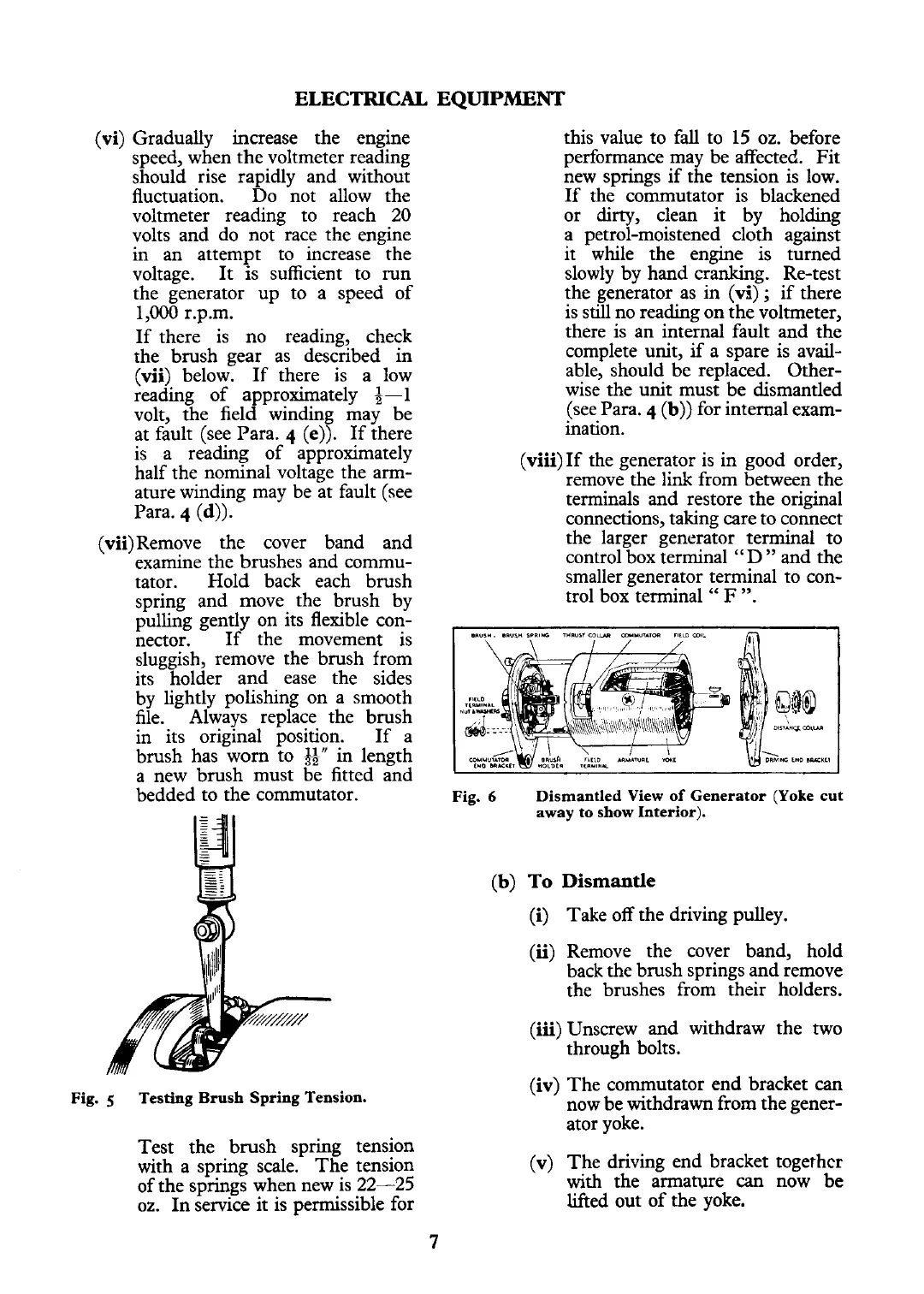
Fig.
6
Dismantled View of Generator (Yoke cut
away to show Interior).
(b)
To
Dismantle
(i)
Take off the driving pulley.
(ii) Remove the cover band, hold
back the brush springs and remove
the brushes from their holders.
(iii) Unscrew and withdraw the two
through bolts.
(iv) The commutator end bracket
can
now be withdrawn from the gener-
ator yoke.
(v) The driving end bracket
togerhcr
with the armature
can
now
be
lifted out of the yoke.
 Loading...


