(vi)
The driving end bracket,
which
on removal from the yoke has
withdrawn with it the arma'iure
and armature shaft ball-bearing,
need not be separated
from the
shaft unless the bearing is sus-
pected and requires examination,
or the armature is to be replaced
;
in this event the armature should
be removed from the end bracket
by means of a hand press.
Commutator
A
commutator in good condition will
be smooth and free from pits or
burned spots. Clean the commutator
with a petrol-moistened cloth. If
this is ineffective, carefully polish
with a strip of he glass paper while
rotating the armature. To remedy a
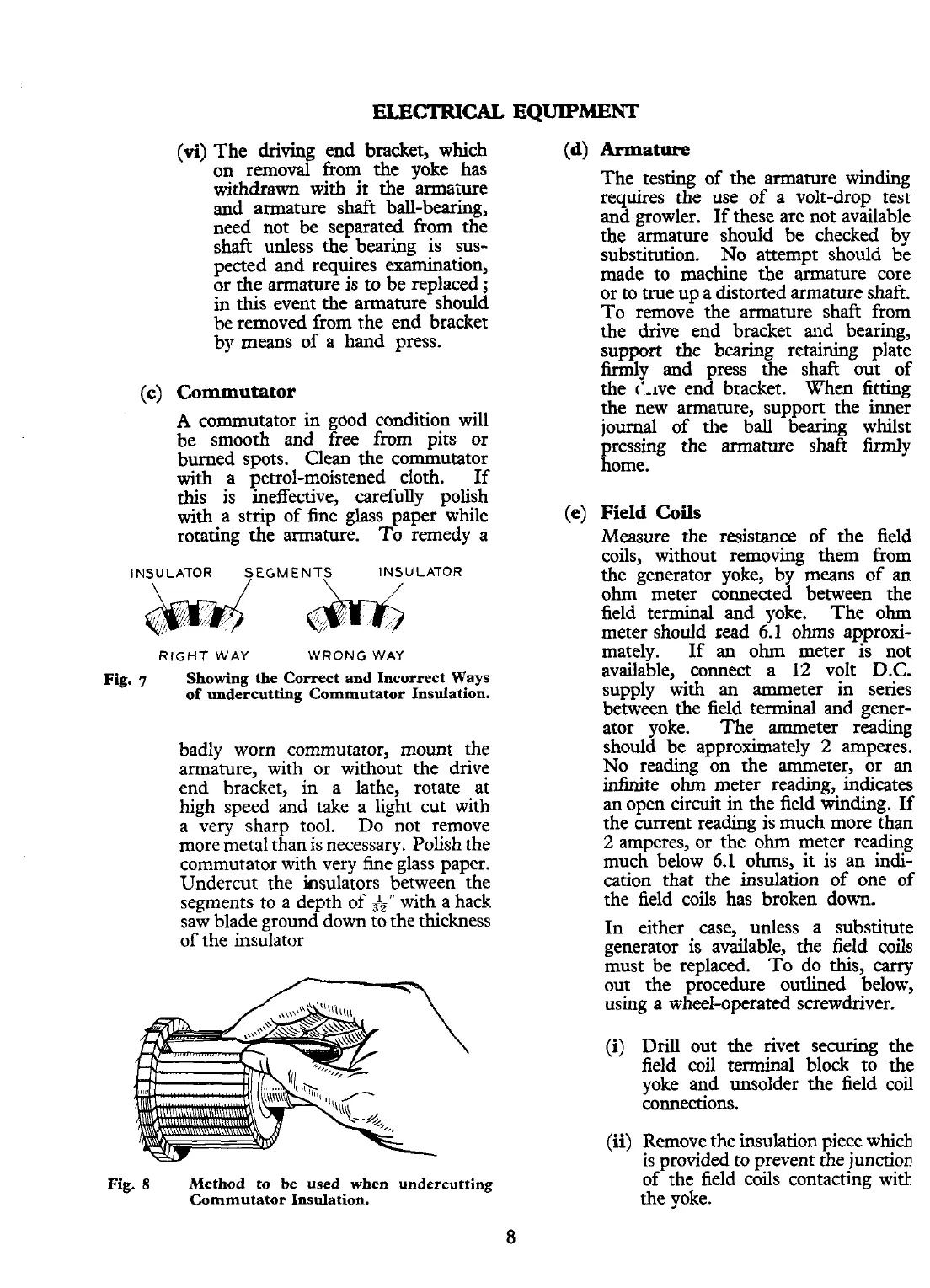
INSULATOR
SEGMENTS
INSULATOR
RIGHT
WAY WRONG
WAY
Fig.
7
Showing the Correct and Incorrect Ways
of undercutting Commutator Insulation.
badly worn commutator, mount the
armature, with or without the drive
end bracket, in a lathe, rotate at
high speed and take a light cut with
a very sharp tool. Do not remove
more metal than is necessary. Polish the
commutator with very fine glass paper.
Undercut the insulators between the
segments
to
a depth of
31,"
with a hack
saw blade ground down to the thickness
of the insulator
Fig.
8
Method to be used when undercutting
Commutator Insulation.
8
Armature
The testing of the armature winding
requires the use of a volt-drop test
and growler. If these are not available
the armature should be checked by
substitution. No attempt should be
made to machine the armature core
or to true up a distorted armature
shafc.
To remove the armature shaft from
the drive end bracket and bearing,
support the bearing retaining plate
firmly and press the shaft out of
the
c'.~ve end bracket. When fitting
the new armature, support the inner
journal of the ball bearing whilst
pressing the armature shaft firmly
home.
Field
Coils
Measure the resistance of the field
coils, without removing them from
the generator yoke, by means of an
ohm meter connected between the
field terminal and yoke. The ohm
meter should
read
6.1
ohms approxi-
mately. If an ohm meter is not
available, connect a 12 volt
D.C.
supply with an ammeter in series
between the field terminal and gener-
ator yoke. The ammeter reading
should be approximately
2
amperes.
No reading on the ammeter, or an
infinite ohm meter reading, indicates
an open circuit in the field winding. If
the current reading is much more than
2
amperes, or the ohm meter reading
much below
6.1
ohms, it is an indi-
cation that the insulation of one of
the field coils has broken down.
In either case, unless a substitute
generator is available, the field coils
must be replaced. To do this, carry
out the procedure outlined below,
using a
wheel-operated screwdriver.
(i)
Drill out the rivet securing the
field coil terminal block to the
yoke and unsolder the field coil
connections.
(ii)
Remove the insulation piece which
is
provided
to
prevent the junction
of the field coils contacting witb
the
yoke.
 Loading...


