ELECTRICAL
EQUIPMENT
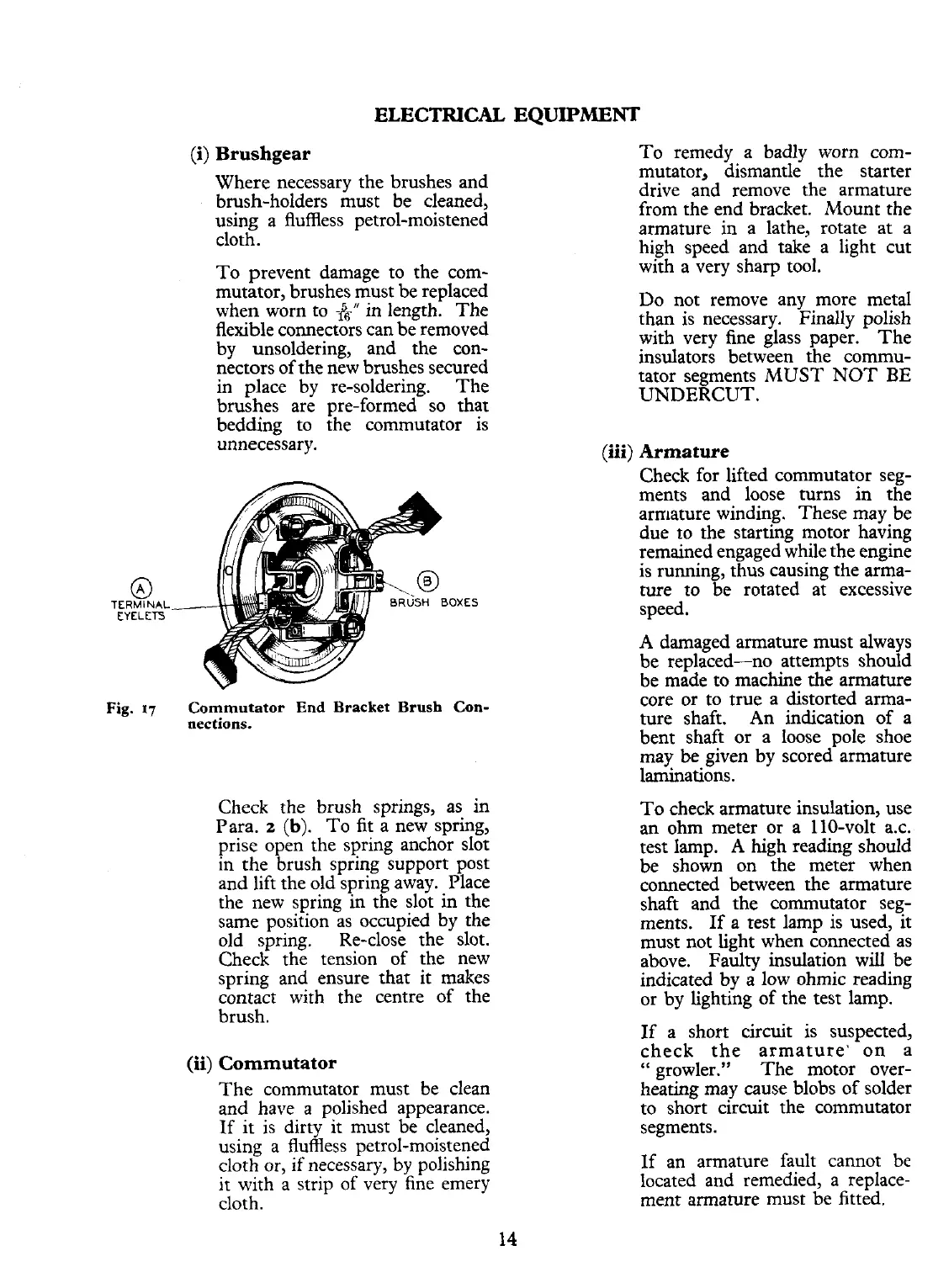
TERMINAL
EYELtrj
(i)
Brushgear
Where necessary the brushes and
brush-holders must be cleaned,
using a fluffless petrol-moistened
cloth.
To prevent damage to the com-
mutator, brushes must be replaced
when worn to
-fgn
in length. The
flexible connectors can be removed
by unsoldering, and the con-
nectors of the new brushes secured
in place by re-soldering. The
brushes are vre-formed so that
bedding to
;he commutator is
unnecessary.
Fig.
17
Commutator
End
Bracket Brush
Con-
nections.
Check the brush springs, as in
Para.
2
(b).
To fit a new spring,
prise open the spring anchor slot
in the brush spring support post
and lift the old spring away. Place
the new spring in the slot in the
same position as occupied by the
old spring. Re-close the slot.
Check the tension of the new
spring and ensure that it makes
contact with the centre of the
brush.
(ii)
Commutator
The commutator must be clean
and have a polished appearance.
If it is dirty it must be cleaned,
using a fluffless petrol-moistened
cloth
or,
if necessary, by polishing
it with
a
strip of very fine emery
cloth.
To remedy a badly worn com-
mutator, dismantle the starter
drive and remove the armature
from the end bracket.
Mount the
armature in a lathe, rotate at a
high speed and take a light cut
with a very sharp tool.
Do not remove any more metal
than is necessary. Finally polish
with very fine glass paper.
The
insulators between the
comrnu-
tator segments MUST NOT
BE
UNDERCUT.
(iii)
Armature
Check for lifted commutator seg-
ments and loose turns in the
armature winding. These may be
due to the starting motor having
remained engaged while the engine
is running, thus causing the arma-
ture to be rotated at excessive
speed.
A damaged armature must always
be replaced-no attempts should
be made to machine the armature
core or to true a distorted arma-
ture shaft. An indication of a
bent shaft or a loose pole shoe
may be given by scored armature
laminations.
To check armature insulation, use
an ohm meter or a 110-volt
a.c.
test lamp. A high reading should
be shown on the meter when
connected between the armature
shaft and the commutator seg-
ments. If a test lamp is used, it
must not light when connected as
above. Faulty insulation will be
indicated by a low ohmic reading
or by lighting of the test lamp.
If a short circuit is suspected,
check the armature' on a
"
growler." The motor over-
heating may cause blobs of solder
to short circuit the commutator
segments.
If an armature fault cannot be
located and remedied, a replace-
ment armature must be fitted.
 Loading...


