ELECTRICAL EQUIPMENT
RUBBER RLTAINING SLEEVE CONTROL PEG PINION WING
UNIT
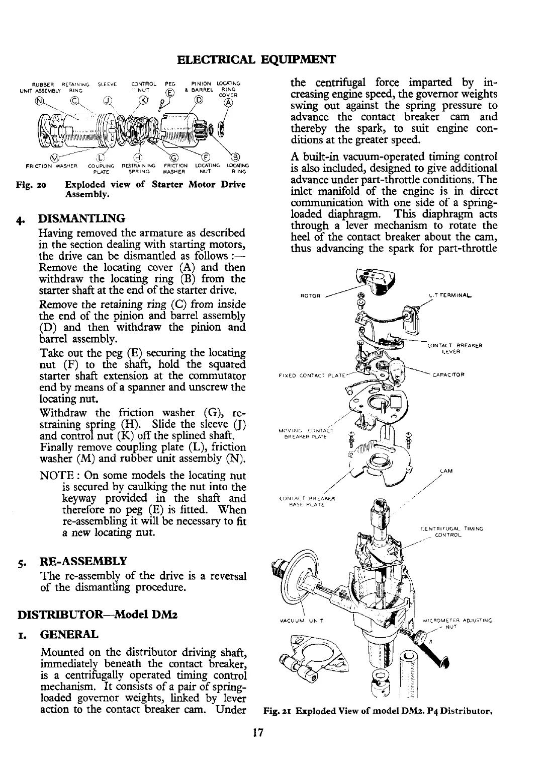
the centrifugal force imparted by in-
creasing engine speed, the governor weights
swing out against the spring pressure to
advance the contact breaker cam and
thereby the spark, to suit engine con-
ditions at the greater speed.
A
built-in vacuum-operated timing control
FRICTION WASHER COVPilNG
RDTRMNIffi
FRICTION WUTING UKAIffi
?LATE
SPRING
W~SHER
NUT
RING
is also included, designed to give additional
Fig.
zo
Exploded view of Starter Motor Drive
advance under part-throttle conditions. The
Assembly.
inlet manifold of the engine is in direct
communication with one side of a spring-
4.
DISMANTLING
loaded diaphragm. This diaphragm acts
through a lever mechanism to rotate the
Having removed the armature as described
heel of the contact breaker about the cam,
in the section dealing with starting motors,
thus advancing the spark for part-throttle
the drive
can
be dismantled as follows
:-
Remove the locating cover
(A)
and then
withdraw the locating ring
(B)
from the
starter shaft at the end of the starter drive.
ROTOR
3
@
8.
T TERMINAL
Remove the retaining ring
(C)
from inside
the end of the pinion and barrel assembly
(D)
and then withdraw the pinion and
barrel assembly.
NTACT BREAKER
Take out the peg (E) securing the locating
nut (F) to the shaft, hold the squared
starter shaft extension at the commutator
FIXED
CONTACT
PLATE'
end by means of a spanner and unscrew the
locating nut.
Withdraw the friction washer
(G),
re-
straining spring (H). Slide the sleeve
(J)
MCVNG
CONTACT
and control nut
(K)
off the splined shaft.
BREAnt~
bin,t
Finally remove coupling plate
(L),
friction
washer
(M)
and rubber unit assembly
(N).
NOTE
:
On some models the locating nut
is secured by caulking the nut into the
keyway provided in the shaft and
CONTACT BRE
BASE PLATE
therefore no peg (E) is fitted. When
re-assembling it will be necessary to fit
a new locating nut.
<.LNTRIrUGAL TlMlNC
5.
RE-ASSEMBLY
The re-assembly of the drive is a reversal
of the dismantling procedure.
DISTRIBUTOR-Model DM2
VACUUM
UNIT
I.
GENERAL
Mounted on the distributor driving shaft,
immediately beneath the contact breaker,
is a centrifugally operated timing control
mechanism. It consists of a pair of
spring-
loaded governor weights, linked by lever
action to the Contact breaker
cam.
Under
Fig.
zr
Exploded View of model DM2.
P4
Distributor.
17